An optical modulator is a device which can be used for manipulating a property of light — often of an optical beam, e. Depending on which property of light is controlled, modulators are called intensity modulators, phase modulators, spatial light modulators, etc. The beam may be carried over free space, or propagated through an optical waveguide (optical fibre). This lets devices send lots of data fast and without mistakes. This process dynamically alters properties of an optical carrier wave—such as amplitude, phase, frequency, or polarization—to embed data. These devices play a crucial role in modern optics and photonics, enabling the manipulation of light for various applications. An optical modulator is a critical component in the realm of photonics and optical communications, playing a pivotal role in manipulating light to encode. Optical modulation allows one to control an optical wave or to encode information on a carrier optical wave. The inverse process that recovers the encoded information is demodulation. According to the.
[PDF]
The Semiconductor Optical Amplifier (SOA) plays a vital role in boosting data transmission for long-distance fiber optic networks. Unlike traditional electronic amplifiers, SOAs amplify optical signals directly without converting them to electrical form. This article focuses on Semiconductor Optical Amplifiers (SOAs), Thulium-Doped Fiber Amplifiers (TDFAs), Praseodymium-Doped Fiber Amplifiers (PDFAs), and Hybrid Amplifiers. This method maintains data integrity over. Explore the functioning, types, advantages, and limitations of Semiconductor Optical Amplifiers (SOA) in modern optical communications. Primarily seen in telecommunication systems as Fiber-Pigtailed components, these components operate at signals. A key player in this arena is the Semiconductor Optical Amplifier (SOA).
[PDF]
In this blog, we will explore the step-by-step process of using a beamsplitter cube effectively, along with some common applications that benefit from this powerful optical tool. Step-by-Step Guide on Using a Beamsplitter Cube. 📦 For purchasing, use the RP Photonics Buyer's Guide for beam splitters. It provides an expert-curated supplier directory, buyer-focused technical background information, and structured selection criteria to support professional procurement decisions. What are Beam Splitters? A beam splitter (or. An Optical Beamsplitter is an optic or optical device that is used to split a beam of light in two. Newport offers a wide variety of Beamsplitters in various shapes. It is a crucial part of many optical experimental and measurement systems, such as interferometers, also finding widespread application in fibre optic telecommunications. One beam is typically reflected while the other is transmitted. The ratio of reflected to transmitted light can vary based on the design of the beam splitter. Our plate beamsplitters have a coated front surface that determines the beam splitting ratio while the back surface is wedged and AR coated in order to minimize ghosting and interference effects.
[PDF]
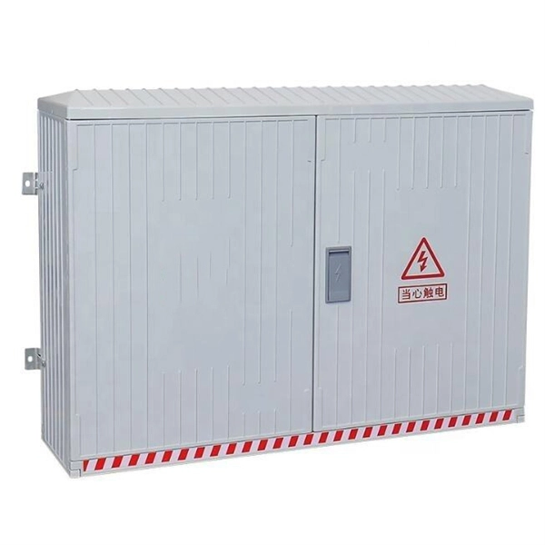
The panel box contains a series of circuit breakers or fuses that control the distribution of electrical energy to individual circuits throughout the building. An electrical panel box, also known as a breaker box or a distribution board, is a crucial component of any electrical system. It serves as a central hub for distributing electricity throughout a building, ensuring that power is delivered safely and efficiently to all the required locations. In this article, we'll explain what a series circuit is, how to draw a series circuit diagram, calculate. A distribution board or distribution box is where the main power supply is distributed to multiple loads. And all the switching and protective devices are installed in the distribution box. Single Phase Distribution Box generally consists of Double Pole MCBs, Single Pole MCBs, and RCCBs. Distribution. STEP 1: The flow of electricity begins at the g nerating station. at S the ation Switchyard. This is done to minimize the losses. STEP3: The ransmission Substation, increases the step-up voltage transformer from 69,000 to 765,000 volts. The distance it will go and the type of facilities distributed.
[PDF]
Appropriate Ethernet cables must be used to connect with the PoE and normal switch by means of a physical connection. Use the cables correctly and plug each end cable to the corresponding port on each switch to provide stable networking. So, the PoE switch is a networking device through which the PoE passes. In addition, this switch has numerous Ethernet ports that link to network segments, which also help with power and data. Can I use a PoE switch as a regular switch? (Answered) A POE switch gives power to devices that support the protocol, like cameras and access points. A regular switch, on the other hand, merely supplies the internet signal. A regular. A PoE switch simplifies network installation by providing power and data transmission over a single Ethernet cable. However, to take full advantage of a PoE switch, it's crucial to understand how to use it properly. This eliminates the need for separate power adapters, reducing cable clutter and. Just reuse teh POW cables that are alredy up there, and instead of them connecting to POE Wifi adapters, connect them to a POE switch (which would also allow me to add more cameras later) and drop a line from that switch into the main switch in the house. In this article we will uncover the subject matter of PoE switches and watch how they are necessary for the network design.
[PDF]

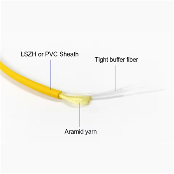
Optical fiber technology has revolutionized the way we communicate, enabling fast and reliable data transmission over long distances. In this article, we will explore the different types of optical fibers used in communication systems and their applications. Fiber Optics or Optical Fiber is a technology that transmits data as a light pulse along a glass or plastic fiber. An Optical Fiber is a cylindrical fiber of glass that is hair-thin in size or any transparent dielectric medium. The fiber which is used for optical communication is waveguides made of. Optical fibers are the backbone of modern communication. They transmit light signals over long distances with minimal loss. Let's break down their classification in a simple and engaging way: 1. The less signal damage metal wires can cause, the better for optical fiber connection. Total internal reflection (critical angle, using Snell's law). Higher bandwidth (extremely high data transfer rate). Less signal degradation. Less costly per meter. Lighter and thinner then copper wire. The light is a form of carrier wave that is modulated to carry information. The cladding's refractive index is slightly smaller than that of the core, which confines light within the core and propagates by repeated total reflection at the boundary with the.
[PDF]
An optical amplifier is a device that amplifies an optical signal directly, without the need to first convert it to an electrical signal. Optical amplifiers are used to create laser guide stars which provide feedback to the adaptive optics control systems which dynamically adjust the shape of the mirrors in the largest astronomical telescopes. An illustration of the effective gainis given below. Note the presence of a gain peak around 1530nm and. Optical amplifiers are a key component in modern optical communication and networking systems. While EDFAs dominate the C/ L bands (~1530–1600 nm) and Raman amplifiers enhance long-haul performance, other amplifier types extend coverage and functionality. In this comprehensive guide, we will explore the fundamentals and applications of optical amplifiers. An optical amplifier is a device that boosts the strength of an optical signal. Typical fiber cables experience a loss of about 0. 2dB per kilometer for 1. To compensate for these losses at regular.
[PDF]
View result: The primary current will be displayed instantly in Amperes. Tips for better accuracy: Always use correct units (kVA, volts). Double-check voltage values. Choose the correct phase system. The formula depends on the transformer type. Primary Current (I) = Power (VA) / Voltage. The primary formula for calculating current in a single-phase AC circuit is derived from the relationship between power, voltage, current, and power factor: This equation assumes a sinusoidal waveform and is applicable to resistive and inductive loads. To simplify calculations, constants can be. Input primary voltage: Enter the input voltage in Volts (V). Select phase type: Choose between single-phase or three-phase. Click calculate: Press the button to get the result. It is easy to visualize the current flowing out of a battery, through a light bulb, and back to the battery. There is a voltage rise across the. It involves using a straightforward formula to generate your kVA requirements from the current and voltage of your electrical load. In the guide to transformer kVA ratings below, we'll explain in more detail how to calculate the required capacity kVA rating. Electricity is carried from the transmission system to individual consumers. Distribution substations connect to the transmission system and lower the transmission voltage to medium voltage ranging between 2 kV and 33 kV.
[PDF]
Finally, use the following formula to determine the busbar current. Calculate the current carrying capability of a 150 (width) x 25 (thickness) (in mm) busbar in the copper material. 2 Ibb = 4500A Click here for more Electrical Calculators IEC 60865-1:. Copper busbar current carrying capacity (ampacity) is the maximum electrical current a copper busbar can safely conduct without overheating or failure, a critical parameter for electrical panel and power distribution design. 2 and IEC 60364 standards ensures copper busbar. To calculate Busbar Current, enter the width (mm), thickness (mm), and material carry capacity factor (amps/mm^2). The electrical power system consists of many incoming & outgoing feeder connections, for which busbars are necessary. A busbar is just a node (conductor or collection of conductors). Even though a busbar looks like just a flat copper or aluminum strip, its size determines how much electrical load it can handle. If the size is too small, it can overheat, cause voltage drop, or even become a fire hazard. If it is oversized, it increases cost and space requirements unnecessarily. Busbars are critical components in electrical distribution networks, typically used to distribute high current among various circuits. 2 A/mm² for copper busbars in enclosed panels and up to 2. 2 Copper busbars have approximately 60% higher current carrying capacity than.
[PDF]
Answer: The current transfer ratio (CTR) is an important parameter in optocoupler selection. The gain of an optocoupler is expressed as the Current Transfer Ratio (CTR). It is defined as the ratio of the phototransistor output current (Ic) to the LED input current (If), expressed as. The current transfer ratio is a parameter similar to the DC current amplification ratio of a transistor (h FE) and is expressed as a percentage indicating the ratio of the output current (I C) to the input current (I F). The CTR has the following characteristics and is therefore as important as the. An optocoupler, also known as photocoupler or opto-isolator, is a device which can transfer an electrical signal across two galvanically-isolated circuits by way of optical coupling. Transferring signals over a light. As I understand the optocoupler current transfer ratio, CTR is like the hfe of a transistor. I can't understand if the CTR is or isn't a critical value and for what applications is it used in. Optocouplers contain both a light-emitting diode (LED) and a photo detector. The current transfer ratio. The current transfer ratio (CTR) refers to the ratio of the collector current at the output side I c to the input current passed to the LED at the input side I F expressed as a percentage. It is defined by the following formula.
[PDF]
adults (49%) say they mostly get news because they happen to come across it, up from 39% in 2019. Over 1,500 new data centers are in development nationwide. Most will be built in rural areas, particularly the South and Midwest, marking a shift from urban. About half of U. Considering how important they are for supporting business operations, ensuring uptime, and enabling scalability, it is a good idea to know what is in a data center, how they work, and. Teens largely turn to TikTok, Instagram and Snapchat for fun and connection. But experiences around messaging, screen time and cyberbullying vary. And what teens say about how these sites impact their mental health. What types of news do Americans seek out or happen to come across? About half of. Data centers are foundational infrastructure for the modern economy. In short, they are the computers we use but don't touch. They power essential services ranging from cloud computing and online commerce to artificial intelligence and secure financial transactions. As the scale and scope of.
[PDF]