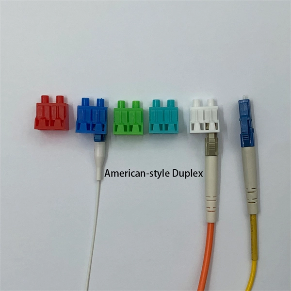
Explore our comprehensive SFP optical module selection guide for 2025. Learn about crucial factors like data rate, distance, fiber type, and compatibility to optimize your network performance and cost-effectiveness. Make informed decisions for your networking needs today!. SFP (Small Form-factor Pluggable) is a compact, hot-pluggable network interface module used to connect network devices (switches, routers, firewalls) to fiber optic or copper cables. They're essential for extending network distances and increasing bandwidth capabilities. Selecting the correct SFP module is not simply a matter of matching connectors. In modern Ethernet networks, choosing the wrong transceiver can result in link failures, speed mismatches, compatibility errors, or unexpected distance limitations. For network engineers, system integrators, and IT. At the core of these advanced networks are bidirectional SFP modules, also known as BiDi SFP transceivers—compact, cost-efficient devices that support high-speed data transmission and reception over a single optical fiber. By using different interfaces and single-mode or multimode fiber depending on the.
[PDF]
A spot network typically comprises a secondary network that serves a singular, concentrated load, such as a high-rise building or shopping mall, necessitating a high level of reliability. The secondary spot netw.
[PDF]
View result: The primary current will be displayed instantly in Amperes. Tips for better accuracy: Always use correct units (kVA, volts). Double-check voltage values. Choose the correct phase system. The formula depends on the transformer type. Primary Current (I) = Power (VA) / Voltage. The primary formula for calculating current in a single-phase AC circuit is derived from the relationship between power, voltage, current, and power factor: This equation assumes a sinusoidal waveform and is applicable to resistive and inductive loads. To simplify calculations, constants can be. Input primary voltage: Enter the input voltage in Volts (V). Select phase type: Choose between single-phase or three-phase. Click calculate: Press the button to get the result. It is easy to visualize the current flowing out of a battery, through a light bulb, and back to the battery. There is a voltage rise across the. It involves using a straightforward formula to generate your kVA requirements from the current and voltage of your electrical load. In the guide to transformer kVA ratings below, we'll explain in more detail how to calculate the required capacity kVA rating. Electricity is carried from the transmission system to individual consumers. Distribution substations connect to the transmission system and lower the transmission voltage to medium voltage ranging between 2 kV and 33 kV.
[PDF]
Answer: The current transfer ratio (CTR) is an important parameter in optocoupler selection. The gain of an optocoupler is expressed as the Current Transfer Ratio (CTR). It is defined as the ratio of the phototransistor output current (Ic) to the LED input current (If), expressed as. The current transfer ratio is a parameter similar to the DC current amplification ratio of a transistor (h FE) and is expressed as a percentage indicating the ratio of the output current (I C) to the input current (I F). The CTR has the following characteristics and is therefore as important as the. An optocoupler, also known as photocoupler or opto-isolator, is a device which can transfer an electrical signal across two galvanically-isolated circuits by way of optical coupling. Transferring signals over a light. As I understand the optocoupler current transfer ratio, CTR is like the hfe of a transistor. I can't understand if the CTR is or isn't a critical value and for what applications is it used in. Optocouplers contain both a light-emitting diode (LED) and a photo detector. The current transfer ratio. The current transfer ratio (CTR) refers to the ratio of the collector current at the output side I c to the input current passed to the LED at the input side I F expressed as a percentage. It is defined by the following formula.
[PDF]

The video tutorial demonstrates the depin and repin method for repairing automotive wiring harness connectors, specifically pigtails. It outlines seven easy steps to replace a pigtail connector, making it accessible for DIY enthusiasts and individuals dealing with electrical issues. This comprehensive guide will equip you with the knowledge and skills to accurately assess the integrity of a pigtail, helping you identify issues before they escalate into larger problems. We'll explore different testing methods, delve into the interpretation of multimeter readings, and offer. The latest in the line of Ford Flex Probe Kits, this newest release includes all the probes from the previous “D” kit, but now adds two each of the Micro Pin (. Additionally, all probes will now be printed with the tip size, helping technicians ensure usage of the properly sized tip. Short answer: An automotive wiring pigtail is a short section of wire with a pre-attached connector that lets you repair or replace a damaged plug without replacing the entire harness. It provides a plug-and-play repair solution that restores OEM fit, seal, and electrical reliability. Key steps. At FindPigtails. com, we specialize in high-quality, OEM connector replacement. Why pay thousands for a complete wire harness, when you can simply replace the damaged connector? We invite you to take a look at some of our instructional videos, for step-by-step guides of de-pin and re-pin procedures.
[PDF]
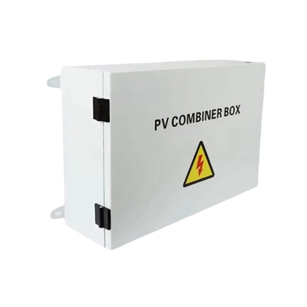
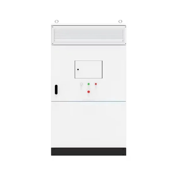
An electrical transformer box is a protective, enclosed unit containing a distribution transformer, which steps down high-voltage electricity to lower, usable voltages for homes and businesses. A newly constructed residential area introduces a 10kV power line to a substation. From the transformer's low-voltage side (0. 4kV), power is distributed to a main distribution panel (primary distribution box). From there, it is routed to individual building distribution boxes (secondary. Electric power distribution is the final stage in the delivery of electricity. Electricity is carried from the transmission system to individual consumers. Distribution substations connect to the transmission system and lower the transmission voltage to medium voltage ranging between 2 kV and 33 kV. Primary distribution systems consist of feeders that deliver power from distribution substations to distribution transformers. Many feeders leave substation in a concrete ducts and are routed to a nearby pole. These boxes feature bottom entry and exit cables, front-opening doors, and main busbars connected with copper strips for optimal contact. They also include metering systems, ensuring.
[PDF]
The inside of a transformer box represents a sophisticated electrical system designed to convert voltage levels efficiently and safely. This essential component houses various critical elements, including the core, windings, insulation materials, and cooling mechanisms. These boxes are commonly seen as green metal units on a concrete pad in neighborhoods with underground. An electrical transformer box safely houses components that regulate voltage for power distribution. Common in residential, commercial, and industrial areas, it ensures efficient power delivery, overload protection, and voltage conversion within local electrical distribution systems. The core, typically made. This tutorial makes transformer boxes easy to understand, describes the different varieties and their parts, and teaches you how to stay safe and fix problems with confidence. When electrical utilities produce electricity and send it out over power lines to our towns and neighborhoods, it's too powerful for us to just use as-is. It safeguards the electrical connections, insulation materials, and oil-filled compartments from external factors such as weather conditions.
[PDF]
This video shows real on-site footage of electrical installation, demonstrating safe and standardized wiring methods used by professionals. more Learn how to wire a distribution box step by step! This video shows real on-site footage of. An electrical panel box, also known as a breaker box or a distribution board, is a crucial component of any electrical system. It serves as a central hub for distributing electricity throughout a building, ensuring that power is delivered safely and efficiently to all the required locations. In this video, we'll walk you through the process of wiring a home distribution box with a detailed connection diagram. Whether you're an electrician or a DIY enthusiast, this guide will help you understand the basics of home electrical distribution. What is Distribution Board? Distribution board. In the USA and Canada (following NEC and CEC), distribution transformers typically receive 4. 2 kV on the primary side and step it down to 120V single-phase and 120/240V split-phase for residential applications. The primary side of the distribution transformer is supplied by two conductors. A well-chosen and properly installed distribution box can prevent electrical hazards, reduce downtime, and ensure your electrical system operates smoothly for years to come. Let's explore how these critical components work and why they deserve your attention. However, the key to.
[PDF]