In an Ethernet patch panel diagram, each port on the patch panel is represented by a numbered or labeled square or circle. The diagram typically includes details such as the port numbers, cable types, and the devices connected to each port. Ethernet patch panel diagram is a visual representation of the connections between Ethernet cables and network devices, such as switches and routers. It provides a clear overview of how the network is structured, allowing network administrators to easily troubleshoot and manage the network. This information can be used to track the location of devices, their serial numbers, and their IP addresses. Change Management: Patch panel connection diagrams can be used to track. A patch panel is an essential component in a network system that provides a central location for connecting multiple devices or cables. The patch panel serves as. A pair of managed Gigabit Ethernet rack-mount switches, connected to the Ethernet ports on a few Panduit patch panels using Category 6 patch cables. (All equipment is installed in a standard 19-inch rack. Each port has a patch connection that links it to another port in another part of your building.
[PDF]
Learn how to identify and prevent these common issues. Installing a fiber optic patch panel may seem straightforward, but many network issues originate from small installation mistakes. Poor fiber routing, incorrect bend radius, or improper labeling can all lead to signal loss, maintenance difficulties, and unexpected downtime. This article highlights. What Can Go Wrong with Copper Patch Panels? What Can Go Wrong with Copper Patch Panels? Are you aware of the problems that a copper patch panel can cause in your network infrastructure? Learn how to identify and prevent these common issues. However, installation errors can lead to issues that impact network performance. This article offers guidance on proper installation and troubleshooting. Network patch panel, cable manager, network cable, wire stripper, crimping tool, zip ties. Use a small yellow tool or wire stripper to remove the outer jacket of the network cable. Cut off the cross-shaped skeleton of the Cat6 patch cord. Insert. Our guide delivers actionable, step-by-step best practices for rack layout, cable management, and patch panel installation. Many seasoned pros (and plenty of first-timers) run into avoidable pitfalls that turn a simple installation into a costly headache.
[PDF]

The complete process for terminating cable runs at a patch panel, from mounting and cable management to punch-down, labeling, and testing every port. To wire a patch panel: Mount the panel in your rack. If you're still deciding which panel style fits your site (keystone vs punch‑down vs pass‑through), start with How to choose a patch panel and come back here once the hardware is locked in. 60-second answer If you want reliable results, the winning recipe is simple: keep pair twists tight right up. Network patch panel, cable manager, network cable, wire stripper, crimping tool, zip ties. Use a small yellow tool or wire stripper to remove the outer jacket of the network cable. Cut off the cross-shaped skeleton of the Cat6 patch cord. Insert. Patch panels make cable management and network organization very easy over long periods of time, but you'll need to wire the panels in order to put them into your network. Not to worry, this guide will walk you through the whole process. Before you jump into the task, ensure that you have the. Testing a patch panel is an essential task to ensure the reliability and efficiency of a network infrastructure. The process verifies the end-to-end connection, ensuring the cable is properly terminated at the wall jack and at the distribution point, such as a switch or patch panel.
[PDF]
In September 2012, NTT Japan demonstrated a single fiber cable that was able to transfer 1 per second (10 bits/s) over a distance of 50 kilometers. Although larger cables are available, the highest strand-count single-mode fiber cable commonly manufactured is the 864-count, consisting of 36 ribbons each containing 24 strands of fiber. These high fiber count cables are used in, and as distribution cables in and networks.
[PDF]
A patch panel is a passive hardware unit that consolidates multiple network connections in one location. Typically rack-mounted, it features ports on the front for easy access and termination points at the back for permanent cabling. From the outside, network planning can look like “run cables, place a switch, get the internet working. By linking wall outlets or devices to network switches through. Ever opened a server room and felt like you walked into a jungle of tangled cables? You're not alone. Businesses of all sizes wrestle with messy wiring, slow troubleshooting, and inconsistent connectivity. But here's the thing: it doesn't have to be that way. The unsung hero behind neat, efficient. We manufacture globally recognized cable management systems and tools designed for your network racks. Explore our product brochure, NIS2 whitepaper, and much more. designed to u2028help you understand our solutions and make informed decisions. Discover who we are and how we're shaping the future. Enter the dynamic duo of **patch panels and racks**: your knights in shining armour against cable clutter. Imagine them as multi-port outlets, neatly organising incoming and outgoing. A fiber patch panel is a mounted enclosure—either rack-mounted or wall-mounted—used to terminate, manage, and interconnect multiple fiber optic cables. It acts as a hub for organizing splices and patch cords, streamlining fiber management and preserving signal integrity. Cable Organization:.
[PDF]

Cable Trays* — Max two 24 in. (610 mm) wide by max 6 in. (151 mm) deep open-ladder cable tray with channel-shaped side rails formed of 0. 54 mm) thick aluminum or min 0. In practice, cable tray dimensions are a system of interrelated measurements —width, depth, length, and material thickness—that directly affect cable fill compliance, heat dissipation, structural loading, and long-term expandability. From an engineering standpoint, cable tray dimensions are not. Perforated Cable Tray System expertly constructed from high-grade stainless steel, offering exceptional durability and resistance to corrosion. With side height 100mm. A properly designed and installed cable tray system will provide. Studs — Wall framing to consist of wood studs or channel shaped steel studs. Wood studs to consist of nom 2 by 4 in. Additional studs shall be used to completely frame. Best Size: Here, deep trays (75mm to 150mm) are used since power cables are typically thick and heavy. Data cables, such as your Wi-Fi or computer ones, are extremely sensitive. They do not get hot; however, they do not like to hang or sag. In case a data cable folds in an excessive manner, the. ect the minimum bend ra-dius for cables as they exit the bottom of the cable tray. A rung spacing of 6 to 9 inches (150 to 230 mm) is preferable when the cable tray cont d for instrumentation and control applications that require additional protec eferred to support and protect numerous small.
[PDF]
Connecting fiber optic cable directly to a standard Ethernet port is not possible. Ethernet ports are designed for copper cables (like Cat5e or Cat6), which transmit data using electrical signals. The process to connect fiber optic cable to router requires careful attention to detail, but I'll walk you through every critical step with the precision and clarity you deserve. This comprehensive guide combines industry standards with field-tested practices to ensure you achieve a rock-solid. In this guide, we'll walk you through how to connect a fiber optic cable to a router safely and efficiently. Why Use Fiber Optic Internet? Before diving into the setup, let's quickly recap why fiber optics are worth the effort: Lightning-fast speeds (up to 1 Gbps or higher). Here's a step-by-step guide to help you through it. Check compatibility: Before you begin, make sure your router supports fiber optic connection. Not all routers can connect directly to a fiber cable, so it is important to verify this information before continuing. Gather. Unlike regular electrical wires, these glass fibers can snap or bend too far. Proper connectors, clean ends, and a good splice keep everything sharp and stable. When you connect the fiber optic cable correctly, you keep your fiber internet, ONT (optical network terminal), and router running at peak. Connecting a fiber optic cable to a router involves a few key steps and specialized equipment.
[PDF]
Patch panels remain indispensable for medium-to-large networks due to their cost savings, flexibility, and organization benefits. However, scalability constraints and niche applications require careful planning. A patch panel is one of those components that is easy to overlook when planning a network — it does not switch, route, or process data, and to the uninitiated it can look like an expensive way to add an extra set of connectors between the cable and the switch. In practice, it is the component that. A patch panel is a centralized hardware component used to manage network cables in data centers, enterprise server rooms, and smart buildings. According to Grand View Research, the global structured cabling market is projected to reach $15. 6 billion by 2030, with patch panels playing a pivotal role. That's where patch panels come in. In this blog, we'll. Patch panels help achieve this by organizing connections, simplifying maintenance, and improving overall cable management in structured cabling systems. Disclosure: As an Amazon Associate, this site earns from qualifying purchases. Whether in data centers, business or home networks, patch panels streamline cable management, improve troubleshooting and enhance overall network performance. Let's learn more.
[PDF]
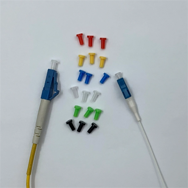
Once you have your modules and fiber in hand, the process is simple: Insert the SFP modules into the SFP or SFP+ port of your UniFi device. Plug in the fiber cable, LC connectors click right into the module. Power on both devices. Watch for a link light, if you see green . LC connectors are quickly becoming the connector of choice due to their compact size and outstanding performance. This guide will walk you through the key steps for properly connecting LC fiber connectors. LC fiber connectors feature a small form factor design that takes up very little space. LC (Lucent Connector) fiber connectors are small form-factor connectors widely used in telecommunications and data center environments. These connectors feature a push-pull coupling mechanism and a 1. 25mm ferrule, making them ideal for high-density applications. Understanding how to properly. By following these steps and precautions, you can ensure a reliable and high-quality connection with LC fiber connectors, enhancing the stability and performance of your network. The abbreviation LC for fiber optic connectors stands for Lucent Connector and literally means “translucent/transparent. The LC connector is about half the size of an SC connector. It meets TIA/EIA-604-10 standards, ensuring compatibility and performance across manufacturers. Learn how to use LC connectors for efficient networks.
[PDF]

Excavate the cable at the break point and use a fiber optic cutter to remove the damaged section. Use a high-precision fiber cleaver to prepare the fiber ends for splicing. Step1 : Identify the optical cabinet and network operating center, and find the fiber optic splitter. Step 2: Identify the splitter number. Step 4: Find the optical fiber port and cable sequence that leads to the user. 2) The. Here are the steps to patch a fiber cable. Make sure the connectors are free from dust or dirt and that there is no damage to the cable's. When fiber cables sustain damage, specialized repair techniques help restore connectivity and maintain data integrity. This comprehensive guide outlines professional fiber optic repair protocols that align with industry best practices. Adhering to precise methodologies, we can mend impaired cables. Learn how to splice fiber optic cable step by step in this complete guide! In this video, you'll see the full fiber splicing process — from fiber preparation, cleaving, and fusion splicing to final testing. Whether you're a network technician, IT professional, or telecom operator, you'll find practical steps, tools, and tips to restore. By understanding these key elements and following the outlined steps, you can effectively repair fiber optic cables and maintain the high-performance network necessary for today's demanding communication needs. When it comes to ensuring nice network experiences for users, the condition of a fiber.
[PDF]

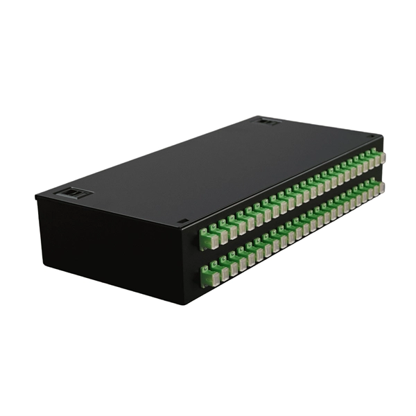
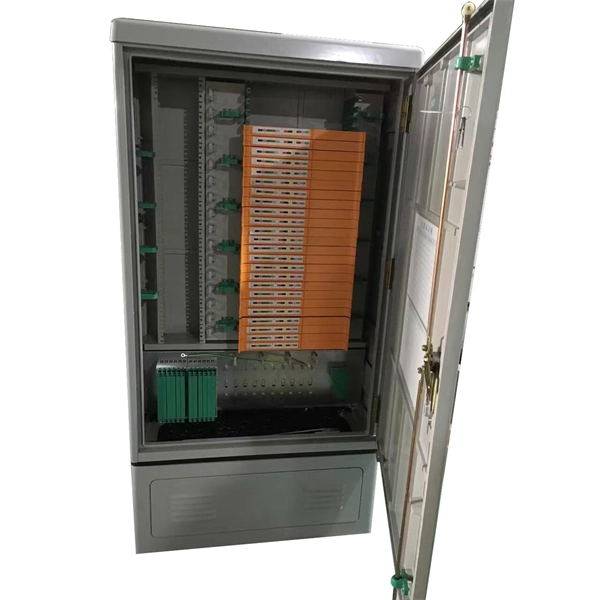
Please view our full RLH price list and contact us at info@fiberopticlink. com if you have any questions or special project needs. A Fiber Optic Patch Panel, also known as an Optical Distribution Frame (ODF) or fiber termination enclosure, is a centralized hardware unit designed to manage, protect, and organize fiber optic cable connections. In an era where data speeds and network reliability are non-negotiable, the patch. fiber optic patch panel, odf, optical distribution frame, fiber distribution panel, rack mount fiber patch panel, wall mount odf, fiber termination box, 1u fiber patch panel, 24 port fiber patch panel, 48 port fiber patch panel, outdoor fiber patch panel, fiber optic odf, sliding patch panel The. Q1: What is the difference between an ODF and a patch panel? An ODF is the entire frame or cabinet managing fiber connections, while a patch panel is a modular unit inside the ODF for cross-connecting fibers. Q2: How many fibers can an ODF handle? It depends on the ODF type; rack-mount units can. ODF is used in the terminal access link of FTTH system. It is a device that splices, distributes, and splits optical fibers and provides protection and management of optical fibers. Belden offers several Fiber Patching Systems. Full patching platforms include FX ECX for LAN environments, FX UHD for high-density fiber channels and the DCX System used primarily in data centers where high amounts of fiber connections and density are the key requirements, as in optical.
[PDF]
When deploying fiber optics in the field, telecommunications companies need ways to safely and efficiently store and terminate cables. As many technicians know, having the right fiber optic patch and splic.
[PDF]
A fiber optic backbone network is the central framework of a network that connects multiple sub-networks, systems, and devices using high-capacity fiber optic cables. It serves as the primary pathway fo.
[PDF]

This comprehensive guide will explore the importance and benefits of this integration, provide an understanding of fiber optic cable and Ethernet ports, discuss their compatibility, and offer a step-by-step process for connecting them. Proper connection of fiber optic cables is essential to harness these benefits fully, as even minor errors can lead to significant performance issues like signal loss. This article will guide you through the necessary tools, materials, and methods on how to connect fiber optic cables effectively. Using an optical cable involves connecting it to the right equipment, ensuring proper installation, and testing the system for optimal performance. Here's a step-by-step guide on how to use optical cable effectively: 1. Check Compatibility of Equipment Ensure that your equipment (e., network. One powerful solution to achieve these goals is by connecting fiber optic cables with Ethernet ports. This comprehensive guide combines industry standards with field-tested practices to ensure you achieve a rock-solid. These transceiver modules are hot-swappable input/output (I/O) devices that plug into 100BASE, 1000BASE and 10GBASE ports (for SFP+), which connect the module port with the fiber-optic or copper network. The SFP transceiver modules are hot-pluggable I/O devices that plug into module sockets. The number one cause of signal loss in optical fiber installations is dirt on.
[PDF]

A ladder type cable tray tee is a fitting used to create a branch in a cable tray system, allowing cables to be routed in three directions. Its "T" shape provides a secure and efficient way to split cables from a main tray into two separate paths, ensuring organized and flexible. A cable tray tee and tee cover are components used in cable management systems to support and protect electrical and data cables. Here's a brief explanation of each:. Rigid steel cable tray tee fitting with zero tangent, safety bottom, and full accessory support. ventilation to heat producing cable such as power communication and other with the same or different width of the cable run. All fittings are available in sizes and types corresponding to the straight cable tray sections. These fitting are including: elbow, horizontal cross, vertical inside. NOTE : Equal or un equal tees can be supplied. When ordering state widths W1xW2xW3.. Office: 147/22 Nguyen Sy Sach Street, 15 Ward, Tân Binh Dist, HCMC,VN. Is it possible to connect 2 cabletrays with a "branch piece (left picture)" instead of a "tee (right picture)". The tee has 3 connectors, the branch piece only has 1 connector. I would like to ajust the "Type properties -> Fittings -> Tee" with the branch family, but can't get it accomplished.
[PDF]