
Whether you're an electrician or a DIY enthusiast, this tutorial will help you understand the fundamentals of wiring a distribution box for a residential setup. Hey, in this article we are going to see the Single Phase Distribution Box Wiring Diagram and Connection Procedure. A distribution board or distribution box is where the main power supply is distributed to multiple loads. And all the switching and protective devices are installed in the. The DB panel board controls the flow of electricity. It protects homes and industries from electrical hazards. It ensures that circuits are safe, organized, and easy to manage. A properly installed electrical distribution box is important for. Electrical systems power our homes, offices, and industrial facilities, but behind every reliable electrical setup lies a crucial component that often goes unnoticed: the distribution box. This essential piece of equipment serves as the nerve center of your electrical system, managing power flow. Welcome to our channel @Electricalgenius In this video, we'll take you through a detailed step-by-step guide on wiring a home distribution DB (Distribution Board) box. Distribution. Distribution box The system diagram usually shows the electrical connection and configuration inside the distribution box in a graphical way, including busbars, circuit breakers, fuses, load devices and other elements. In practical applications, the corresponding system diagram can be drawn.
[PDF]
Mouser offers inventory, pricing, & datasheets for LC Adapter Fiber Optic Connectors. Corning's extensive line of of LC (lucent connector) connectors offer great performance with very high repeatability and low insertion loss. These products are fully intermateable with standard LC licensed products and deliver long-term stability under a broad range of applications and conditions. 5 mm ferrule connectors without sacrificing performance. LC connectors are available in industry-standard beige (multi-mode), blue (single-mode), and green (angle polish) colors, and will accommodate 900 µm buffered fiber, 1. 6 mm, 2 mm. Search the world's information, including webpages, images, videos and more. Google has many special features to help you find exactly what you're looking for. The name WYSIWYGTM is a trademark of CAST Lighting Limited. Microsoft® and Windows® are registered trademarks of Microsoft Corporation in the United States and other countries. HP and Compaq and the names of HP and Compaq products. Fibertronics offers a variety of LC fiber optic adapters. These are also known as LC fiber optic mating sleeves and are available in both single mode and multimode variants with either a zirconia sleeve or bronze sleeve. Hybrid. Fiber Optic Connectors Mini-Com Duplex Keyed/Non-Keyed LC Adapter Module Keyed B-Red Adapter half on User side and No key on Service Side.
[PDF]

This report covers the optical, environmental, and mechanical performance of the LC-UPC, singlemode fiber optic BOAs, provided by Tyco Electronics, Fiber Optics Business Unit. Qualification testing was completed by a third party in July 2004. IDEAL FOR DEBUGGING OPTICAL POWER PERFORMANCE & OPTICAL INSTRUMENT CALIBRATION CORRECION & FIBER SIGNAL ATTENUATION. As optical passive devices, FS attenuators are mainly used in fiber optic to debug optical power performance & optical instrument calibration correction & fiber signal. L-com offers an extensive line of dual wavelength (1310/1550nm) Singlemode fiber optic attenuators. These versatile in-line attenuators are the perfect solution for attenuating Singlemode fiber connectors for both lab and commercial applications. Constructed of the highest quality materials and. zation system's perfo. the power of an optical signal. Our LC/APC single mode attenuators can handle a maximum o 1 watt of optical input power. This device contains one ale and one female LC/APC port. LC/APC optical attenuators can be ordered in attenuation. Fixed loopback type attenuators from OMC offer defined control of optical signals in both integrated and add-on products. Depending on the project or need, fixed attenuators can limit (attenuate) the amount of light passing through to the exact levels your project or application requirement.
[PDF]
LC connectors play an integral yet often overlooked role in enabling high-speed fiber optic communications. This guide dives into the engineering behind these compact connectors, their functionality, performance metrics, and applications across modern networks. LC connectors are a ubiquitous fiber. LC connectors provide reliable and high performance connectivity in fiber optic networks. The guide covers in depth their features, types, installation techniques, troubleshooting and applications. Learn how to use LC connectors for efficient networks. As a small-form-factor (SFF) interface, LC has become the default duplex connector in enterprise LANs, telco closets, and data-center topologies because it balances density, repeatability, and cost. This guide walks. It covers LC connectors, LC patch cables, uniboot designs, armored and ultra-low-loss variants, LC adapters and patch panels, LC attenuators, MTP/MPO-to-LC cassettes, LC-interfaced transceivers, and LC media converters. It also includes practical selection guidance, real-world deployment scenarios. Fiber optic connector is a device used to connect optical fibers, capable of transmitting and receiving optical signals. There have been many types of connectors developed for fiber cable. Single mode networks have used FC or SC.
[PDF]

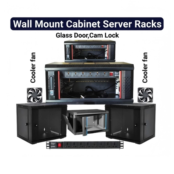
In this guide, you will learn how to interpret network diagrams like a pro, from symbols and scope to segmentation, dependencies, troubleshooting, and security clues. A rack elevation diagram is a visual representation of the equipment and components contained within a rack in a data center or server room. It provides a clear overview of the physical layout of the rack, including the placement and positioning of servers, switches, storage devices, and other. Learn how to read and interpret network diagrams effectively to troubleshoot, validate security, and plan network changes with confidence. Have you ever opened a network diagram and felt like you were staring at a subway map with no station names? That is a common problem, even for experienced IT. Network cabinet cabling describes the structured connection and arrangement of all IT components in a server rack. The aim is a secure, maintainable and scalable operation of the network environment. The amount. A standard operating procedure, or SOP, is a set of step-by-step instructions compiled by an organization to help workers carry out complex routine operations. Work instructions should be very detailed on "how" to accomplish a specific job, task or assignment. It helps teams understand network architecture, data flow, and dependencies, making it easier to design infrastructure, troubleshoot issues, and plan.
[PDF]
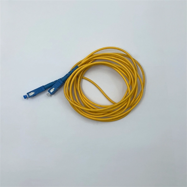
The LC optical fiber pigtail is designed with a push-pull mechanism, enabling easy installation and removal without compromising on performance. Executive Summary: A fiber optic pigtail is one of the most commonly specified yet least understood components in structured cabling. Get the wrong connector type, the wrong polish, or skip proper fusion splicing technique—and you're looking at elevated signal loss, increased back reflection, and a. Fiber pigtails are simple in appearance, yet essential in function. They are the bridge between fiber optic cables in the field and the equipment or patch panels that manage them. By combining factory-installed connectors with spliced bare fiber, pigtails ensure that network installers can create. Fiber optic network design refers to the specialized processes leading to a successful installation and operation of a fiber optic network. It includes first determining the type of communication system (s) which will be carried over the network, the geographic layout (premises, campus, outside. All Rights Reserved. fCONSTRUCTION QUALITY REQUIREMENTS FOR FTTP & SSP Work Orders This document provides Construction Technicians, Construction Managers, FTTP/SSP Vendors, and Inspectors with the essential information to ensure a quality build and to successfully pass an Outside Plant Inspection. These terminations must be of the right style, installed in a.
[PDF]
The 2025 Fiber Deployment Cost Annual Report, produced by the Fiber Broadband Association and Cartesian, provides the industry's most comprehensive benchmark of fiber build costs across the U. Drawing on data from operators and contractors in 38 states, the report shows that. Fiber optic network projects for industrial and oil and gas applications typically cost $15,000-50,000 per mile for aerial installation and $30,000-80,000 per mile for direct burial. Budgeting requires accounting for design, permitting, materials, labor, splicing, testing, and a 15-20% contingency. Buyers typically pay for fiber laying by combining material costs, labor time, and permitting plus trenching or aerial support fees. The main cost drivers are trench depth, fiber count and type (single-mode vs multi-mode), conduit requirements, and local permitting rules. This guide provides clear cost estimates, price ranges. Site Survey and Planning The first and most critical step in fiber optic network construction is the site survey—also known as a field survey. Engineers and planners assess the project area to determine the most efficient routes for the fiber optic installation. This information can help project leaders engage with providers and network operators in their area. This data is based on cost information.
[PDF]
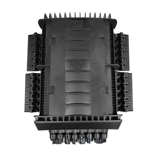
For TDM-PON, a passive optical splitter is used in the optical distribution network. In the upstream direction, each ONU (optical network units) or ONT (optical network terminal) burst transmits for an assigned time-slot (multiplexed in the time domain). In this way, the OLT is receiving signals from only one ONU or ONT at any point in time. In the downstream direction, the OLT (usually) continuously transmits (or may burst transmit). ONUs or ONTs see their own data through the address labels embe.
[PDF]
A beam splitter or beamsplitter is an optical device that splits a beam of light into a transmitted and a reflected beam. It is a crucial part of many optical experimental and measurement systems, such as interferometers, also finding widespread application in fibre optic telecommunications. DesignsIn its most common form, a cube, a beam splitter is made from two triangular glass which are glued together at their base using polyester,, or urethane-based adhesives. (Before these synthetic,. Beam splitters are sometimes used to recombine beams of light, as in a. In this case there are two incoming beams, and potentially two outgoing beams. But the amplitudes. For beam splitters with two incoming beams, using a classical, lossless beam splitter with Ea and Eb each incident at one of the inputs, the two output fields Ec and Ed are linearly related to the inputs thro.
[PDF]

