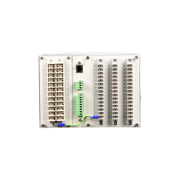
In an Ethernet patch panel diagram, each port on the patch panel is represented by a numbered or labeled square or circle. The diagram typically includes details such as the port numbers, cable types, and the devices connected to each port. Ethernet patch panel diagram is a visual representation of the connections between Ethernet cables and network devices, such as switches and routers. It provides a clear overview of how the network is structured, allowing network administrators to easily troubleshoot and manage the network. This information can be used to track the location of devices, their serial numbers, and their IP addresses. Change Management: Patch panel connection diagrams can be used to track. A patch panel is an essential component in a network system that provides a central location for connecting multiple devices or cables. The patch panel serves as. A pair of managed Gigabit Ethernet rack-mount switches, connected to the Ethernet ports on a few Panduit patch panels using Category 6 patch cables. (All equipment is installed in a standard 19-inch rack. Each port has a patch connection that links it to another port in another part of your building.
[PDF]
【Terminal Versatility】- Each 12V marine busbar features 5 x M6 (1/4”) stainless steel terminal studs for positive and negative connections, ensuring secure and efficient power distribution. Check each product page for other buying options. Price and other details may vary based on product size and color. Need help?. These bars are tin-plated copper and have stainless steel terminals. Also known as bus bars, they serve as connection points between wires with ring or spade terminals. The underside is sealed, so the bars can be safely mounted to conductive surfaces. Distribution Bar Covers— Distribution bar. Our automotive busbars and terminal blocks allow you to consolidate wiring and distribute electrical power in a cost-effective manner. So, what's the difference? A busbar. Pricing (USD) Filter the results in the table by unit price based on your quantity. Busbar Barrier Terminal Blocks are available at Mouser Electronics. Mouser offers inventory, pricing, & datasheets for Busbar Barrier Terminal Blocks. Pick compact mini bus bars, high amp PowerBar and MaxiBus models, and 4 to 20 circuit terminal blocks with covers for clean marine, vehicle, RV, and bench wiring. Shop terminal blocks, barrier strips, and DC bus bars.
[PDF]

Run the display transceiver [ interface interface-type interface-number | slot slot-id ] [ verbose ] command to view information about the optical module on a specified interface. In optical communication equipment, an optical module (Optical Module) contains several types of semiconductor chips that work together to complete the transmission and processing of optical signals. These chips typically include laser chips, photodetector chips, driver chips, transimpedance. When the optical module on an interface is faulty, you can run the display commands to view information about the optical module. Today, we will deeply analyze the four mainstream models of 100G QSFP28 dual-fiber optical modules: QSFP28-100G-SR4, QSFP28-100G-LR4, QSFP28-100G-ER4 and. The following uses the Moduletek SFP-10G-LR module connected to a Huawei S6700 switch as an example to introduce how to read information of the connected optical module on a Huawei switch. Figure 1 Schematic Diagram of Optical Module Connected to Switch 1. Optical Module Status Check Run the. Upgrade to 100G or 400G optics and save. Cisco Transceiver Modules - Learn product details such as features and benefits, as well as hardware and software specifications. Network administrators have a major challenge determining the right Cisco SFP modules, understanding complex model numbers that directly affect network performance and stability.
[PDF]
Electric power distribution systems are designed to serve their customers with reliable and high-quality power. The most common distribution system consists of simple radial circuits (feeders) that can be ove.
[PDF]

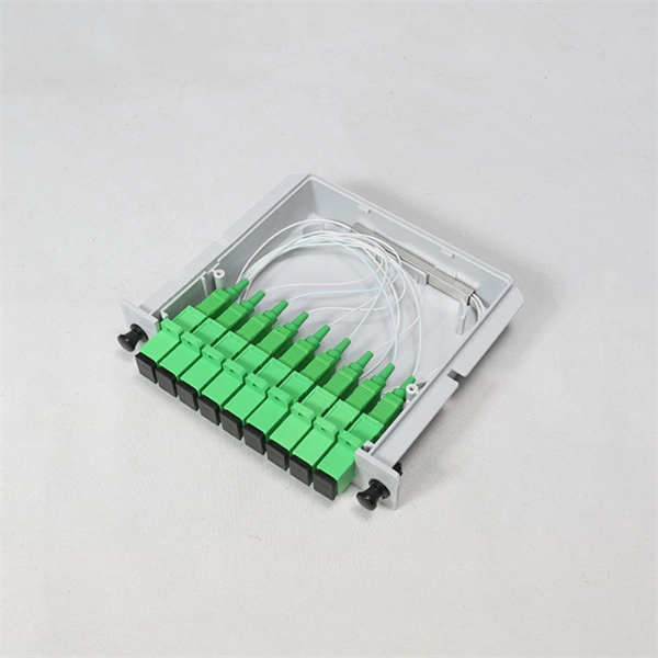
An Optical Splitter, also known as a beam splitter, is a passive optical device that divides a single input optical signal into two or more output signals. Conversely, it can also combine multiple signals into one. Knowing the difference between a splitter and an optical coupler helps you build better networks. You make your network work better when you pick the right device for each job. You can connect many users to one port with 1:n or 2:n splitters. By dividing a single optical signal from a central Optical Line Terminal (OLT) into multiple outputs for Optical Network Terminals (ONTs) at users' homes, splitters eliminate the need for dedicated fibers to each residence—slashing infrastructure costs while scaling network reach. This guide. In a Passive Optical Network (PON), a single optical fiber carries massive amounts of data using light. Signal Input: The fiber splitter receives the optical signal from the upstream network node and enters the splitter through the input fiber. Signal Distribution: Inside the splitter, according to the design structure and different. Splitters are passive optical devices that divide or combine optical signals, and they come in various types, including power splitters, uneven splitters, and wavelength-division multiplexing (WDM) splitters. Each type serves specific applications, enabling efficient use of optical infrastructure.
[PDF]

A ladder type cable tray tee is a fitting used to create a branch in a cable tray system, allowing cables to be routed in three directions. Its "T" shape provides a secure and efficient way to split cables from a main tray into two separate paths, ensuring organized and flexible. A cable tray tee and tee cover are components used in cable management systems to support and protect electrical and data cables. Here's a brief explanation of each:. Rigid steel cable tray tee fitting with zero tangent, safety bottom, and full accessory support. ventilation to heat producing cable such as power communication and other with the same or different width of the cable run. All fittings are available in sizes and types corresponding to the straight cable tray sections. These fitting are including: elbow, horizontal cross, vertical inside. NOTE : Equal or un equal tees can be supplied. When ordering state widths W1xW2xW3.. Office: 147/22 Nguyen Sy Sach Street, 15 Ward, Tân Binh Dist, HCMC,VN. Is it possible to connect 2 cabletrays with a "branch piece (left picture)" instead of a "tee (right picture)". The tee has 3 connectors, the branch piece only has 1 connector. I would like to ajust the "Type properties -> Fittings -> Tee" with the branch family, but can't get it accomplished.
[PDF]

Cable Trays* — Max two 24 in. (610 mm) wide by max 6 in. (151 mm) deep open-ladder cable tray with channel-shaped side rails formed of 0. 54 mm) thick aluminum or min 0. In practice, cable tray dimensions are a system of interrelated measurements —width, depth, length, and material thickness—that directly affect cable fill compliance, heat dissipation, structural loading, and long-term expandability. From an engineering standpoint, cable tray dimensions are not. Perforated Cable Tray System expertly constructed from high-grade stainless steel, offering exceptional durability and resistance to corrosion. With side height 100mm. A properly designed and installed cable tray system will provide. Studs — Wall framing to consist of wood studs or channel shaped steel studs. Wood studs to consist of nom 2 by 4 in. Additional studs shall be used to completely frame. Best Size: Here, deep trays (75mm to 150mm) are used since power cables are typically thick and heavy. Data cables, such as your Wi-Fi or computer ones, are extremely sensitive. They do not get hot; however, they do not like to hang or sag. In case a data cable folds in an excessive manner, the. ect the minimum bend ra-dius for cables as they exit the bottom of the cable tray. A rung spacing of 6 to 9 inches (150 to 230 mm) is preferable when the cable tray cont d for instrumentation and control applications that require additional protec eferred to support and protect numerous small.
[PDF]
The state of a laser's polarization is determined by several anisotropic mechanisms of either the laser gain media or the resonator. "Anisotropic" refers to properties whose values vary in different direct.
[PDF]
The most commonly used primary distribution voltages are 11 kV, 6. Utilities may have some control over and access to the energy stored in electric vehicles attached to the grid. The voltage used for primary distribution depends upon the amount of power to be conveyed and the distance of the substation required to be fed. Due to economic considerations, primary distribution is carried out by. There are five main functions of the distribution substation: Voltage transformation: One or more transformers will always be located within the substation to step down the voltage to the primary distribution voltage level. These transformers will always be three-phase banks, or they will be three. Electric power distribution is the final stage in the delivery of electricity. Electricity is carried from the transmission system to individual consumers. These taps are typically single phase, but may also be two phases or three phases. Laterals can be directly connected to main trunks, but are more commonly protected by protective devices such as fuses. distribution voltages are between 4 and 35 kV. In this article, unless otherwise specified, voltages are given as line-to-line voltages; this follows normal industry practice, but it is sometimes a source of confusion. A voltage class is a.
[PDF]

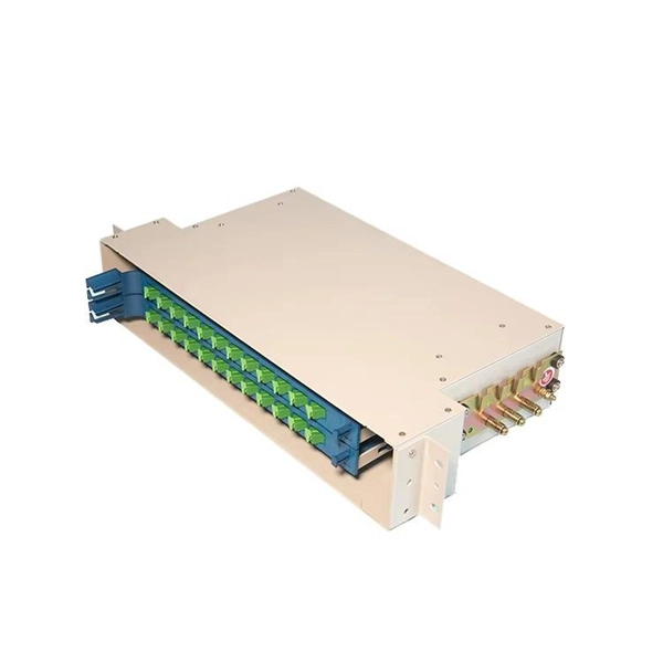
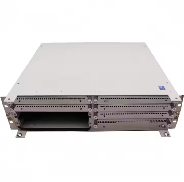
Quick answer: Choose a 12-port or 24-port ODF for small fiber terminations, branch locations, and light distribution needs. In real projects, the right optical distribution frame must match your current fiber count, rack space, adapter format, cable routing method, maintenance habits, and future expansion plan. Many buyers focus only on the initial number of terminations they need today. That often leads to one of two. An Optical Distribution Frame (ODF) is a metal unit that organizes fiber optic connections. It's where incoming and outgoing cables meet. Without it, cables get tangled. This article explores the types, components, applications, installation, and maintenance best practices, providing a. This complete guide explores everything you need to know about ODFs — from their structure, types, and key components, to installation best practices and modern design trends. Whether you're building a central office, data center, or FTTx distribution network, understanding the right ODF. This guide explores the various types of ODFs, their features, and ideal applications. Whether you're setting up a data center, deploying a telecom network, or managing fiber-to-the-home (FTTH) connections, understanding these types will help you select the right solution for efficient, reliable.
[PDF]