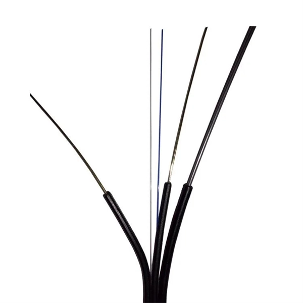
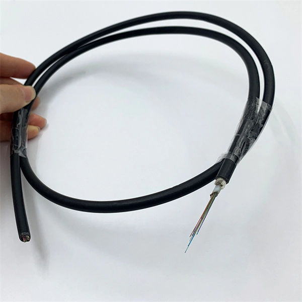
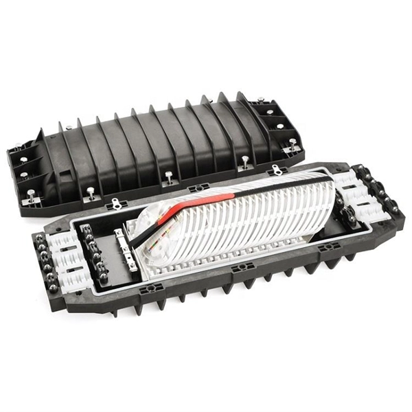
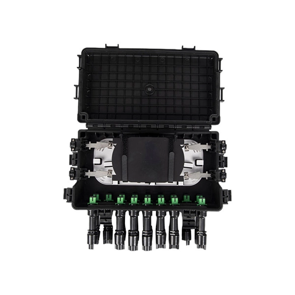
In network cabling, outdoor connections generally use fiber optic cables. When these optical fibers are installed or laid out, a Fiber Termination Box, or FTB, is used to distribute and protect the optical fiber link.
[PDF]

The formula for calculating electrical box size is: . The formula for calculating electrical box size is: . Free electrical load calculation tool for residential and commercial buildings. Calculate service entrance sizing, panel loads, demand factors, and ensure NEC Article 220 compliance. Important: Load calculations must comply with NEC Article 220 and local codes. Always verify calculations with a. How to choose a distribution box of the right size for a project based on load current? If you're like most electrical professionals, picking the right distribution box for your project can feel like navigating a maze. I've been in those shoes - staring at spec sheets, worrying about. The National Electrical Code (NEC) specifies minimum box sizes based on wire gauge and quantity. Proper sizing ensures safety, ease of maintenance, and compliance with regulations. This calculator helps you determine the minimum required box volume based on the number of wires, devices, ground wires, and clamps involved. This ensures compliance with electrical codes and prevents overcrowding. Choose a standard or custom box volume watch capacity update with clear pass or fail status plus tips examples CSV and PDF export for documentation Works for common sizes supports.
[PDF]
You can buy a manufactured 90 degree bend or make one on a cable tray bending machine but in this video I show you how to make one using a metal bar. Students trading aid on how best to put an internal 90 degrees bend in steel cable tray. more. The bends, tees, crosses, risers and reducers of wire mesh cable tray can be easily and quickly made live at the project by using a bolt cutter. Since the jaws of the bolt cutter drags a layer of zinc across the cut end and forms a protective layer. When a wire cable tray is cut, the fact that a. Before bending a cable tray, it is crucial to prepare it properly. This involves a few essential steps to ensure a successful bending process. First, marking is important📏. The space between your lines will be. Below are examples of fabricating the ET range to work around the needs of your electrical install project quickly and efficiently. Always use 2 splice plates per length of tray and SBH and CNH splice nuts and bolts to fasten them in place. EzyStrut splice bolts have a smooth head which should be.
[PDF]
This schematic details the products and procedures for the treat-ment of construction joints/cold joints in new concrete structures. Cold joints occur when a fresh concrete batch is poured against a partially hardened existing layer. As you know, concrete hardens through chemical reactions between cement aggregate, water, and air. This detail uses two elements in addition to ad-ditives and coaings to waterproof. Cold jointing concrete is a technique used to connect two separate concrete pours that have not fully bonded together, often due to delays or interruptions in the pouring process. This method involves preparing the existing concrete surface by cleaning and roughening it, applying a bonding agent to. Eng-Tips is the largest forum for Engineering Professionals on the Internet. Members share and learn making Eng-Tips Forums the best source of engineering information on the Internet! Congratulations GregLocock on being selected by the Eng-Tips community for having the most helpful posts in the. Managing cold joints is an important concept to grasp when working on concrete projects. For the completed structure to be strong and long-lasting, cold joints must be handled correctly. The term "cold" is used because the two concrete layers are not bonded properly, which can result in a weakened.
[PDF]

In the following tutorial, we will show how to wire 120V single-phase and 240V split-phase circuit breakers and loads inside a residential main panel. The figure below shows a typical breaker panel used for 120V and 240V circuits. Messy distribution boxes are dangerous and very hard to fix. You will learn to build a safe, efficient, and professional electrical system today. Circuit breaker wiring configurations involve organizing main switches, busbars. A breaker box, also known as a circuit breaker panel, is an essential component of any electrical system. It is responsible for distributing electricity throughout a building, ensuring that each circuit receives the proper amount of power. To understand how a breaker box works, it is helpful to. Each circuit is protected by a circuit breaker, a safety device that automatically shuts off power if it detects an overload or a fault. If you're looking to replace an old fuse box replacement or upgrade your home's power capacity, you'll be dealing with the load center or service panel. The distinction between 1P and 2P circuit breakers plays a pivotal role in determining the appropriate protection level for various circuits. When installing or troubleshooting a power distribution system, understanding how to correctly connect the main electrical supply to the control panel is crucial.
[PDF]

Cable Trays* — Max two 24 in. (610 mm) wide by max 6 in. (151 mm) deep open-ladder cable tray with channel-shaped side rails formed of 0. 54 mm) thick aluminum or min 0. In practice, cable tray dimensions are a system of interrelated measurements —width, depth, length, and material thickness—that directly affect cable fill compliance, heat dissipation, structural loading, and long-term expandability. From an engineering standpoint, cable tray dimensions are not. Perforated Cable Tray System expertly constructed from high-grade stainless steel, offering exceptional durability and resistance to corrosion. With side height 100mm. A properly designed and installed cable tray system will provide. Studs — Wall framing to consist of wood studs or channel shaped steel studs. Wood studs to consist of nom 2 by 4 in. Additional studs shall be used to completely frame. Best Size: Here, deep trays (75mm to 150mm) are used since power cables are typically thick and heavy. Data cables, such as your Wi-Fi or computer ones, are extremely sensitive. They do not get hot; however, they do not like to hang or sag. In case a data cable folds in an excessive manner, the. ect the minimum bend ra-dius for cables as they exit the bottom of the cable tray. A rung spacing of 6 to 9 inches (150 to 230 mm) is preferable when the cable tray cont d for instrumentation and control applications that require additional protec eferred to support and protect numerous small.
[PDF]

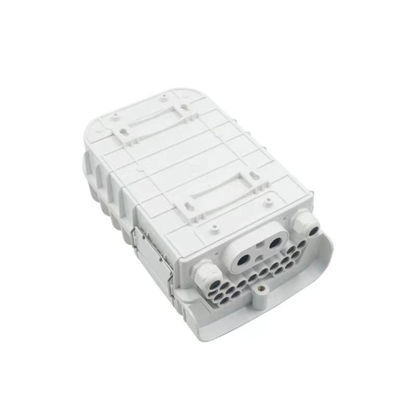
Step-by-step instructions on how to install the Polylok 12" distribution or drainage box. Installing a distribution box is a crucial step in the setup of a septic system, serving as the central hub that directs wastewater from the septic tank to the drain field. This component ensures that effluent is evenly distributed across the leach field, preventing overloading and potential system. maintains a relatively low soil loading rate and provides better effluent treatment. Distribution boxes also provide a readily accessible means of locating the leaching device, making flow adju e typically made of reinforced concrete with plumbing “knock outs” into th box. Frequently-asked questions and answers about septic system distribution boxes or D-boxes: what is a D-box, where is the D-Box, why do we need a D-box, and how do I fix or replace a D-box? In this article series about septic system drop boxes we describe the best procedures for locating and. When installing, please follow the instructions strictly and ensure installation by a professional. Open the terminal chamber cover, connect the cables through the cable gland to the terminals, ensuring both the internal and external ground wires are correctly connected. After confirming there. **I. Installation methods for distribution boxes**1. **Preparation before installation** - **Tool and material preparation** - Prepare the tools requir.
[PDF]
Includes dual power supplies, hot-swappable modules, link aggregation (LAG), and support for HSRP/VRRP. Modular chassis or stackable designs make it easy to scale as your network grows. 1X support, SNMP, CLI/Web GUI, and network access control. There are different types of enterprise switches that perform various roles in these layer-based or hierarchical ethernet networks. This white paper introduces the following three types of network switches and further discusses the selection criteria for each switch. What is a network switch? So, what is a network switch? A network switch is a vital component of a computer network that. What is Spanning Tree Protocol (STP) and why is it important in core switch networks? Can I use a cloud-managed core switch? How does Quality of Service (QoS) impact core switch performance? What Is a Core Switch in Networking? Understanding the Backbone of Your Network A core switch in networking. Providing The Most Competitive Networking Products For Global Customers! In the realm of system networking, three key types of switches are frequently mentioned: access switches, aggregation switches, and core switches. The part of the network that directly connects to user devices is referred to. What Is a Core Switch? The Definitive Guide to Network Architecture A core switch is a high-capacity, high-performance Layer 3 switch positioned at the physical backbone of an enterprise network. This post mainly explores the confusing problem: core.
[PDF]
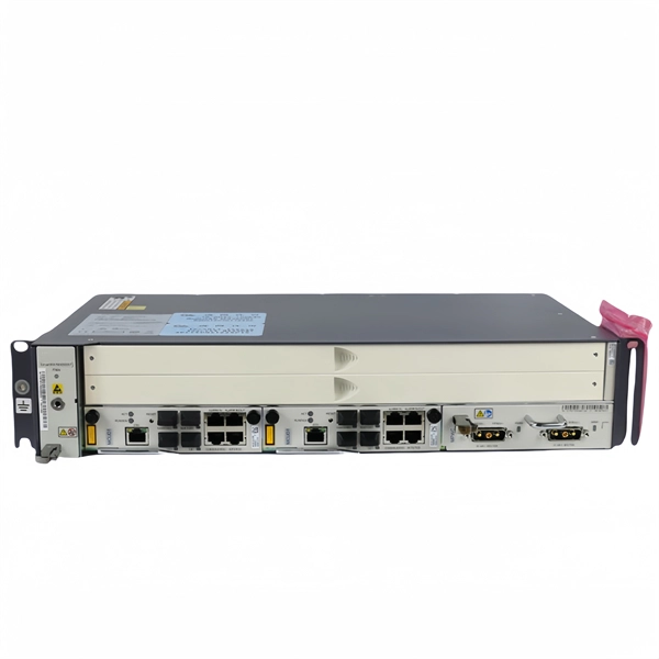
An optical line termination (OLT), also called an optical line terminal, is a device which serves as the service provider endpoint of a passive optical network. It provides two main functions: to perform conversion between the electrical signals used by the service provider's equipment and the fiber optic signals used by the passive optical network.to coordinate the multiplexing between the conversion. FeaturesOLTs include the following features: • A downstream frame processing means for receiving and churning an cell to generate a downstream frame, and converting a parallel dat. Most vendors integrate an entire fiber optic management system for ISPs to manage OLTs as well as client ONTs and as such are not interoperable. • • BT-PON.
[PDF]
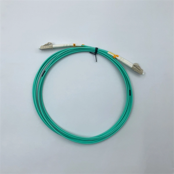
As an essential component of optical fiber communication, optical modules are optoelectronic devices that facilitate the conversion between optical and electrical signals during the transmission process. Operating at the physical layer of the OSI model, optical modules are core devices in optical. That is, metal medium communication represented by coaxial cables and network cables is gradually being replaced by optical fiber media. Optical modules are a core component of optical fiber communication systems. They are used in fiber optic communication systems to transmit data over long distances with minimal loss and interference. These modules typically consist of a laser or LED transmitter, a. An optical module is a typically hot-pluggable optical transceiver used in high-bandwidth data communications applications. As the core optoelectronic devices operating at the Physical Layer of the OSI model, their.
[PDF]
This paper analyzes the basic principle and function of relay protection, summarizes the common fault types, and analyzes the fault analysis methods and treatment measures combined with actual cases. A method of fault tracking for relay protection devices is presented in this paper. Fault tracking means that after the failure of relay protection devices, the anomalies and warning informa-tion are obtained through data-mining technology, and then, the fault tracking algorithm is used. Relay fault diagnosis refers to the process of identifying and analyzing faults or abnormalities in protective relays. However, in actual operation, the relay protection device may cause failure due to hardware failure, software problems or external. For a long time, the fault diagnosis technology of relay protection consists of isolated cases and does not have a systematic method.
[PDF]

Please select a category, brand, and model to find a type-approved device. Results will be displayed here after search. Among these, 1G optical modules stand out as key components, playing a crucial role in facilitating data transfer. To delve into their significance, we'll first explore the definition of 1G optical modules and understand their purpose in the broader context of networking. At its core, a 1G optical. 1G optical modules are designed to operate at a data transfer rate of 1 Gigabit per second (Gbps). These modules are compatible with single-mode and multimode fiber optics, providing flexibility in network setups. 25G and 1G Fiber channel data rates. It is the most popular type in the market and is perfect for use in any location. 1G Optical transceivers come in both commercial and industrial versions so that you. At their core, 1G SFP modules are small optical or electrical transceivers that conform to 1000BASE Ethernet standards. Their function is to change electrical signals coming from switches or routers to optical signals, and vice versa, depending on whether they are being used with fiber or copper. This comprehensive guide aims to delve into the fundamentals, applications, installation, and configuration of 1G optical modules, while also examining the future trends in optical networking.
[PDF]
Epson Device Admin is an application that allows you to install devices on the network, and then configure and manage the devices. The following outlines the main features. A complete multi-vendor reference for GPON/EPON OLT configuration, monitoring & troubleshooting. This repository serves as a technical knowledge hub for network engineers working with FTTH (GPON/EPON) infrastructure. It contains configuration commands, troubleshooting methods, power-check commands. Streamline configuration and management for your Epson printer fleet. With automatic device discovery, this intuitive software helps save. OpManager monitors ZTE-ZXPON-EPON-ONU for health and performance. With the help of our ZTE-ZXPON-EPON-ONU device template, you can easily discover and monitor critical performance metrics without any hassle. This guide dives deep into EPON technology, its benefits over alternatives like GPON, and the critical role of optical modules. Whether you're a network engineer or a tech. This document provides examples of configuring Ethernet Passive Optical Network (EPON). The configuration examples in this document were created and verified in a lab environment, and all the devices. Versatile dual-layer tester purpose-built for PON service activation, with added broadband capabilities. The PPM1 leverages a unique patented technology that makes all the difference in the field.
[PDF]
A passive optical network (PON) is a shared, fiber optic access network that uses unpowered optical splitters to connect many users to a single OLT. PONs deliver high‑speed connectivity with fewer active components than traditional networks, improving reliability and reducing costs. While there are many subtle differences, a clear distinction between active optical networking and PON topology is PON's use of a. A passive optical network (PON) is a system commonly used by telecommunications network providers that brings fiber optic cabling and signals all or most of the way to the end user. In practice, PONs are typically used for the last mile between Internet service providers (ISP) and their customers. They do not need powered devices. This makes them save energy. PON architecture lets one fiber help many users. The main parts of PON are Optical Line Terminals (OLT), fiber. Passive optical networking (PON) is a high-speed broadband technology that enables the delivery of multiple services over a single fiber optic cable. In this article, learn what a PON is, how they work, and their benefits.
[PDF]

Today, our services span home and business, and include complex corporate ICT solutions, cost-effective mobile and landline packages, and the delivery of Fiji's only ultra-fast home fibre broadband. Connecting is a way of life. We're proud to offer you the technology that makes it. Datec (Fiji) Pte Limited specializes in the delivery of information and communications technology solution to businesses in Fiji and Pacific region countries. From its beginning 39 years ago, Datec is now one of the largest technology provider in Fiji and region. Our business has been built on. Location : Amy Street, Toorak,Suva, Fiji Specialising in; Please contact us on how our experienced staff can assist with your telecommunications construction requirements. Always conduct our business in a safe, ethical and environmentally responsible manner. Welcome to ATH, Fiji's premier telecommunications provider, delivering reliable and innovative solutions to connect you with the world. At ATH, we believe in the. We offer a range of solutions to execute your digital transformation We work with a variety of industries to deliver technology solutions. Our aim is to provide our customers, both in Fiji and the wider Pacific region, with intelligent state-of-the-art solutions.
[PDF]