2X2 Fiber Optical Switch connects optical channels by redirecting an incoming optical signal into a selected output fiber. The 2X2 Opto-Mechanical Optical Switches consists of 2 input and 2 output fiber ports that selectively transmits, redirects, or blocks optical power in a fiber. An all-optical Ethernet switch is a network switch whose service ports are entirely optical, meaning every interface uses fiber rather than copper. This design enables end-to-end optical signal transmission, avoiding the conversion between electrical and optical signals at the switch port level. There are no specific requirements for this document. This document is not restricted to specific software and hardware versions. The information in this document was created from the devices in a. The optical ports on the switch are usually paired together, with one TX sender and one RX receiver. The. This gigabit fiber switch has 8-port 1000Mpbs SFP socket and 2ports RJ45 port. The electrical interface will Auto-Negotiate to a 10/100Mbps, or 1000Mbps Ethernet rate without any adjustments. Built on Huawei's unified software platform and equipped with high-performance fully programmable chips, they deliver abundant features including Service Roam.
[PDF]

Optical switches will accept inputs nearly immediately as compared to mechanical switches, which could experience a few milliseconds of debouncing lag. Since optical switches do not depend on physical contact, input latency (latency) is severely minimized. This discrepancy can just be a couple of. An optical transistor, also known as photonic transistor, optical switch or light valve, is a device that switches or amplifies optical signals. Any communication protocol (Ethernet, ATM, etc. Significant. High Speed: Optical switches provide a high-speed data transmission capacity that surpasses that of traditional electrical switches. Interference Resistance: They are immune to electromagnetic interference, ensuring a reliable data transfer. Low Power Consumption: With no need for O-E-O conversion. Optical switching is the process of controlling the destination of individual optical information signals. This technology allows for high bit rate transmission to be switched between various optical lines. The core component enabling optical switching is the Optical Switch. Figure: Optical Switch. Serving as the backbone of high-speed fiber-optic networks, data centers, and emerging technologies like quantum communication, optical switches enable efficient light signal management with a small latency. As global demand for bandwidth surges due to 5G, AI, and cloud computing, advancements in.
[PDF]
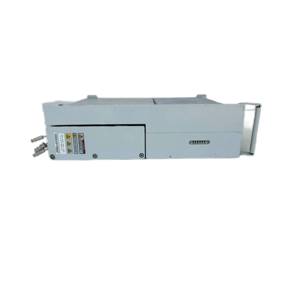
Step 3 Remove the cables or optical modules from the old card. Press the two green locking clips in the middle of the card to eject the ejector levers. Turn the ejector levers outward and slowly pull the card out. Place the replaced. Unplug the optical fibers from the optical module before removing it. Install or remove optical fibers carefully to avoid damaging the fiber connectors. If an optical module cannot be completely inserted into an optical. Page 7 Optical port USB storage device Wi-Fi terminal 1. Wear an ESD wrist strap or ESD gloves when replacing the optical module. Therefore, replace an optical module only when you confirm.
[PDF]
Switches come in three types: those with purely Ethernet ports, those with purely optical ports, and those with a combination of both. Port types are limited to two: optical and Ethernet. Optical ports on switches typically accommodate optical modules for. The optical ports on the switch are usually paired together, with one TX sender and one RX receiver. The. Optical switching represents a fundamental technological evolution, shifting data routing from the domain of electrons to the realm of photons, or light. This transition allows data to remain in its native optical form as it travels through fiber optic networks, eliminating the need for. An all-optical Ethernet switch is a network switch whose service ports are entirely optical, meaning every interface uses fiber rather than copper. This design enables end-to-end optical signal transmission, avoiding the conversion between electrical and optical signals at the switch port level. Copper ports, also known as RJ45 ports, are the most common type of Ethernet switch ports. These ports use twisted-pair copper cables (Cat5e, Cat6, Cat6a, etc. Copper ports are widely used in local area networks (LANs) due to their cost-effectiveness and ease of installation. They can function as core, aggregation, and access devices on campus networks and connect to upstream and downstream devices.
[PDF]

The Huawei S5731-S24T4X is a switch from Huawei's S5731 series, designed for enterprise networks. It is a versatile and high-performance device that supports a range of applications, including data center, campus, and branch networking. The Xingmai Passive Ethernet Network (PEN) is an all-optical campus network solution based on the passive technology. Leveraging mainstream Ethernet protocols, the Xingmai PEN solution uses optical fibers to implement passive data transmission without the need of any ELV room. 24 Gigabit Ethernet Ports: Provides 24 10/100/1000 Mbps. Demand for Wi‑Fi 6-ready campus networks is growing rapidly, the Huawei S5732 Series empowers modern networks as a cutting-edge Aggregation Switch and Campus Switch, offering multi-Gigabit access, PoE++, and service intelligence. Its capabilities—from built-in WLAN AC to VXLAN and MACsec—ensure. CloudEngine S6780-H series switches are Huawei's next-generation enterprise-class core and aggregation switches that provide 64 x 100GE/32 x 25GE ports and 16 x 400GE optical ports. CloudEngine S5732-H hybrid optical-electrical.
[PDF]
There are 48 bicolor LEDs (green/amber) for the first 48 SFP+ ports and 16 tricolor LEDs (green/amber/white) for the SFP-DD ports. The last set of LEDs pulse once in white before indicating the FC port status in green or amber. When it blinks white twice, it shows the status of the second port of the SFP-DD. The port status LEDs for the FC ports are arranged left and right to correspond to the upper and lower ports respectively in each pair. LEDs on the port side of the switch Table 1. LEDs on Cisco Catalyst 9500 Series Switches 1 Available only on switches with 10G ports. System LED Indicator System is not operational. System is operating normally. As a group or individually, the LEDs show information about the switch and about the ports Preventing Overload - Each port that provides PoE has a maximum power it can deliver. Three LEDs are used on each port. Ports on the Cisco Catalyst switch do not have LEDs. Not the question you're searching for? Each. Number of LEDs per port - Ports that cannot be split; for example, 1G ports must have 1 LED per port. Location - A port LED should be placed right above the.
[PDF]
F port is FastEthernet interface and fast Ethernet port, also known as 100M port. It is mainly used to connect switches or computers. When selecting or configuring a network switch, you often encounter ports labeled G, F, E, and S. Understanding the differences between these port types is essential for proper network design, cable selection, and optical module compatibility. Below, we break down each port type in detail. You can use commands to set bandwidth. This article will focus on the four common interfaces: G port, F port, E port, and S port to facilitate understanding before installation. S port The meaning of Serial interface is also called high-speed. S port is fully called serial interface, also known as high-speed asynchronous serial port. E port It is the Ethernet interface. Each Fibre Channel port can be used as a downlink (c onnected to a server) or as an uplink (connected to the data center SAN network).
[PDF]
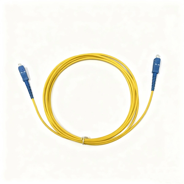
The SFP port is a built-in optical port of a Gigabit Ethernet switch, so it cannot be directly connected with a twisted pair or a jumper. It needs to be connected to an optical module first, and then it can be transmitted with an optical fiber patch cord. This chapter describes how to configure Gigabit Ethernet switching on the Catalyst enterprise LAN switches. Note For complete syntax and. Si ce produit est vendu au Canada, vous pouvez accéder à ce document en français canadien à https://www. com/support/download/. The RJ45 port is for copper cable. al installation guidelines and recommended procedures. To deploy this switch effectively and ensure trouble-free operation it is recommended to first read the relevant sections in this guide so rk administ tors and support personnel that install, e is based h relevant specif tions and. This command is configured in layer-2 interface configuration mode. The optical interface speed is fixed. The optical/electric port cannot support the gigabit and full-duplex at the same time. The ordinary TX port does not. The guidelines for configuring speed on QFX5100-48T switch are as follows: If the speed on the switch is set to 10-Gbps or auto, the switch advertises all the speeds. If you have configured the speed to 100 Mbps.
[PDF]
Unmanaged provides plug-and-play simplicity Auto-speed negotiation Selects individual port speed automatically, depending on client capabilities; removing the need for manual intervention enables simple.
[PDF]
An optical amplifier is a device that amplifies an optical signal directly, without the need to first convert it to an electrical signal. Optical amplifiers are used to create laser guide stars which provide feedback to the adaptive optics control systems which dynamically adjust the shape of the mirrors in the largest astronomical telescopes. An illustration of the effective gainis given below. Note the presence of a gain peak around 1530nm and. Optical amplifiers are a key component in modern optical communication and networking systems. While EDFAs dominate the C/ L bands (~1530–1600 nm) and Raman amplifiers enhance long-haul performance, other amplifier types extend coverage and functionality. In this comprehensive guide, we will explore the fundamentals and applications of optical amplifiers. An optical amplifier is a device that boosts the strength of an optical signal. Typical fiber cables experience a loss of about 0. 2dB per kilometer for 1. To compensate for these losses at regular.
[PDF]
A passive optical network (PON) is a fiber-optic telecommunications network that uses only unpowered devices to carry signals, as opposed to electronic equipment. In practice, PONs are typically used for the last mile between Internet service providers (ISP) and their customers. In this use, a PON has a point-to-multipoint topology in which an ISP uses a single device to serve many end-us. Components and characteristicsA passive optical network consists of an (OLT) at the service provider's central office (hub), passive (non-power-consuming) optical splitters, and a number of (ONUs) or. Passive optical networks were first proposed by in 1987. Two major standard groups, the (IEEE) and the. A PON takes advantage of (WDM), using one wavelength for downstream traffic and another for upstream traffic on a (ITU-T, typically OS2). BPON, EP.
[PDF]
For TDM-PON, a passive optical splitter is used in the optical distribution network. In the upstream direction, each ONU (optical network units) or ONT (optical network terminal) burst transmits for an assigned time-slot (multiplexed in the time domain). In this way, the OLT is receiving signals from only one ONU or ONT at any point in time. In the downstream direction, the OLT (usually) continuously transmits (or may burst transmit). ONUs or ONTs see their own data through the address labels embe.
[PDF]
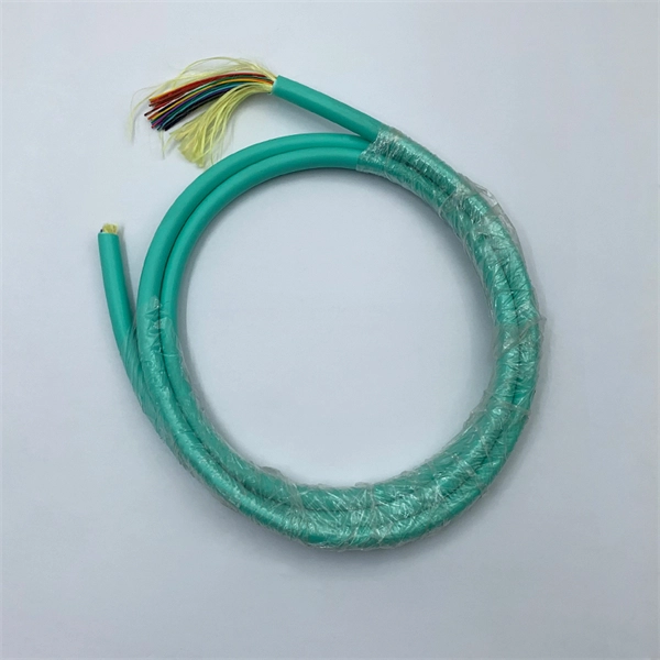
Basic run: 800 ft outdoor fiber drop with aerial installation, minimal trenching, and standard termination. Labor: 12–18 hours; Materials: $1,200; Total: $3,500-$6,000. Homeowners and businesses typically pay for fiber optic cable installation based on distance, conduit needs, and labor. The main cost drivers include material type, run length, trenching or aerial work, and any required permits or inspections. This article provides cost. A simple 1-core FTTH drop cable costs around $0. 13 per foot, while a 288-count optical fiber cable for building backbones can reach $6 per foot or more. Pre-terminated assemblies and patch cables incur higher costs due to factory termination, with prices varying by connector type and the number of. Whether you need singlemode, armored, or indoor plenum, this guide gives you the exact cost per foot of fiber optic cable — including installation — so you can budget without guesswork. Data aggregated from Q1 2026 contractor invoices across Texas, Ohio, and North Carolina. Understanding cost ranges helps buyers budget. Cost of Laying Fiber Optic Cable in the U. The price ranges reflect both ongoing improvements in fiber deployments and regional differences in permitting and crew rates.
[PDF]
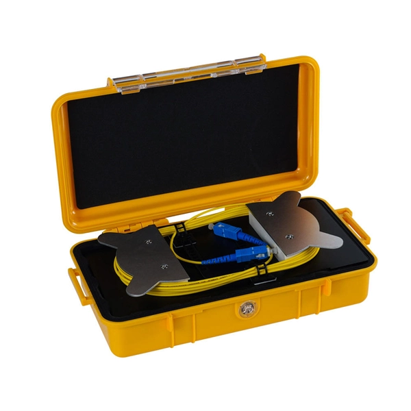
An optical time-domain reflectometer (OTDR) is an optoelectronic instrument used to characterize an optical fiber. It is the optical equivalent of an electronic time domain reflectometer which measures the impedance of the cable or transmission line under test. An OTDR injects a series of optical pulses into the fiber under test and extracts, from the same end of the fiber, light that is scatter. Reliability and quality of OTDR equipmentThe reliability and quality of an OTDR is based on its accuracy, measurement range, ability to resolve and. The common types of OTDR-like test equipment are: 1. Full-feature OTDR: 2. Hand-held OTDR and Fiber break locator: 3. RTU in RFTSs:. In the late 1990s, OTDR industry representatives and the OTDR user community developed a unique data format to store and analyze OTDR fiber data. This data was based on the specifications in GR-196, G.
[PDF]
The main trade show for the large optical module industry is the Optical Fiber Conference (OFC), that is held annually in southern California. Other prominent shows for the industry include ECOC in Europe and FOE in Japan.
[PDF]