Our product meets the specification of Cisco® QSFP56-200G-SR4 and we proudly offer a compatibility guarantee and limited lifetime warranty. Carritech Optics delivers high-performance 200G Transceivers designed to provide ultra-fast, scalable, and efficient connectivity for data centres, cloud networks, and telecom operators transitioning to next-generation infrastructures. Unlocking hyperscale and 5G network performance with 200G. QSFP56-200G-SR4 Cisco® Compatible Transceiver QSFP56 200GBase-SR4 (850nm, MMF, 100m, MPO, DOM) ATGBICS Cisco® Compatible QSFP56-200G-SR4 QSFP56 200GBase-SR4 form factor network transceiver supports a distance of up to 100m over multi-mode fibre (MMF) using a wavelength of 850nm via an MPO-12. Worry-Free 30 Day Returns ( Return shipping cost on us) 5-Year warranty (Exchange New) & Lifetime warranty (Repair) Free Trial & Bulk Price Available Late Shipping till 8pm. 5-YEAR WARRANTY Lifetime warranty for repair. 30-Day Money-back Guarantee. Designed in compact form factors such as QSFP56 and QSFP-DD, these transceivers support 200G. Discovery's Coherent Optical Receivers are designed for 100 Gb and upcoming 200 Gb and 400 Gb fiber optic communication systems. Optical Dual Polarization QPSK (DP-QPSK) and 16 QAM modulation formats are detected and converted to electrical signals that can be fed to a digital storage scope, or. Copyright © Chengdu Superxon Communication Technology Co.
[PDF]

Receiver sensitivity is the lowest optical power level at which an optical receiver can successfully decode data with acceptable bit error rates (BER). It's a core parameter in optical transceiver specifications, indicating the module's capability to detect weak incoming signals. The standards body governing the application sets this specified BER. For example, SONET specifies that the BER must be 10 -10 or better. What Is BER? The bit error rate (BER) measures the data transmission precision within. Receiver sensitivity stands as a critical parameter impacting an optical transceiver's functionality. It denotes a module's capability to function in challenging environments and aids network operators in determining the system's maximum reach or link margin. Lower receiver. Among a group of optical receivers, a receiver is said to be more sensitive if it achieves the same performance with less optical power incident on it. The performance criterion for digital receivers is governed by the bit-error rate (BER), defined as the probability of incorrect identification of.
[PDF]
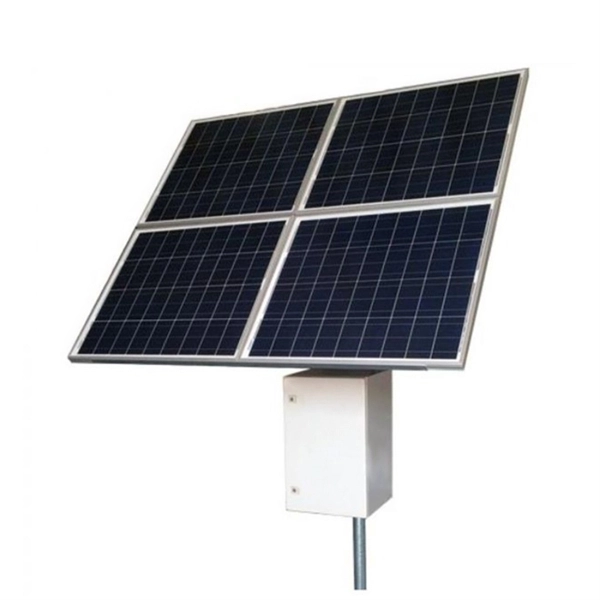
Picking up the best router for fiber internet isn't just about going to the market and choosing one of the best wireless routers. Instead, you need to carefully look at its specs, performance, and the type of securit.
[PDF]
Find all you need for professionally buying optical fiber communication systems and devices: a comprehensive expert-curated directory of suppliers, scientific and technical background information, and an interactive AI-based tool with guidance for a structured decision process. T he MACOM PRISM-50D™MATP-05026D device is a 50G PAM4/NRZ PHY with integrated DSP and multiplexing functionality designed to enable single-wavelength 50G optical transceiver solutions. MACOM PRISM-50D™ is a highly integrated device offering low latency, low power, and a small foot print package. FIBERSTAMP 100G QSFP28 CLR4 optical transceiver are used for medium and long distance interconnection in data centers, complying with 100G CLR4 MSA specification and compatible with both 100G Ethernet and InfiniBand EDR transmission protocols. The product has a built-in pair of 4-channel CWDM MUX. GIGALIGHT 100G QSFP28 LR4 optical modules are used for long-distance transmission in the datacom or telecom field and are compliant with IEEE 802. 3ba 100GBASE-LR4 Ethernet transmission protocol, with optional dual-rate versions compatible with 100G Ethernet and OTN OTU4. The package contains a high-speed DFB laser chip, thermoelectric cooler, thermistor, optical isolator, and a rear-facet monitor. Contact Optilab for more information and pricing options. The Optilab DML-1550-PM-M is a directly modulated laser (DML) module with Polarization Maintaining fiber output at 1550 nm. You appear to be.
[PDF]
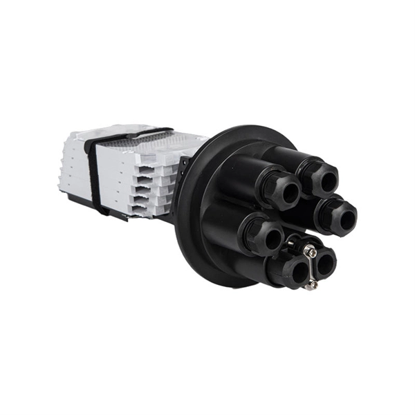
ROSA refers to Receiver Optical Sub-Assembly, the primary function of which is to convert the optical signal transmitted from TOSA into electrical signal. ROSA contains a photodiode (PD), optical interface, metal and/or plastic housing, and electrical interface. This article will focus on the internals of the optical transceiver including the TOSA, ROSA and BOSA, and PCBA. Optical modules are devices used to connect network devices, transmit. As a key element in optical communication systems, optical transceivers serve as media between network devices to transmit and receive data. There has been lots of articles and guides on transceiver modules in the perspective of the package type while only a few of them cover the internal elements. Optical transceivers are essential components in modern telecommunications, facilitating data transfer between various network devices by converting electrical signals to optical signals and vice versa. The following section will focus on. An optical receiver is a device that converts light signals traveling through fiber optic cable back into electrical signals that electronic equipment can process.
[PDF]

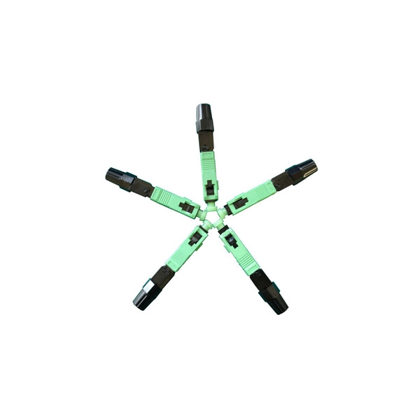
Fiber Optic Bundle Pigtails comprises a set of 12 optical pigtails. For ease of identification, these pigtails will come in 12 different colours and are used to be optically spliced with the optical fibers from the optical cable to enable network connection. Fiber optic pigtails are available in various types: Grouped by pigtail connector type, there are LC fiber optic pigtails, SC fiber pigtails and ST fiber pigtails, etc. And by fiber count, 6 fibers, 12. Fiber Optic Pigtails, also known as pigtailed fibers, consist of an optical fiber connector and a section of optical cable. Characterized by having an optical fiber connector on one end and a bare fiber end on the other, they are primarily used to connect optical transceivers or other optical. They are the bridge between fiber optic cables in the field and the equipment or patch panels that manage them. By combining factory-installed connectors with spliced bare fiber, pigtails ensure that network installers can create fast, reliable, and cost-effective terminations. Without pigtails. Executive Summary: A fiber optic pigtail is one of the most commonly specified yet least understood components in structured cabling. Fiber Optic Bundle Pigtails are. Traditional Fusion Splice-On Connectors with pigtails provide factory-polished performance with field-termination convenience within harsh environments. Mass fusion splicing can fuse up to all 12 fibers in one ribbon at once.
[PDF]

This guide breaks down their technical differences, performance metrics, real-world applications, and how to choose the right one for your network—all optimized for Google SEO and packed with actionable insights. Introduction: Why Fiber Optic Cable Type Matters. Single mode fiber optic cable is made up of a small diameter glass or plastic core surrounded by cladding, which is a layer of reflective material. This small diameter core, typically around 9 microns in diameter, allows only one mode of light to pass through, resulting in a narrower beam of light. But not all fiber cables are created equal: multimode (MM) and single mode (SM) fibers are the two primary types, each engineered for specific use cases, from short-range data center connections to transcontinental telecom backbones. Whether you are an IT specialist, a network manager, or just a curious individual interested in the. As explained by the Fiber Optics Association, fiber optics is the communications medium that sends optical signals down hair-thin strands of extremely pure glass cores. The core is surrounded by the cladding that traps the light in the core. Fiber types are identified by the diameters of the core. The article compares single-mode and multimode fiber optic cables, especially in how their core design, light propagation, and use-cases differ. Core Diameter Single mode fiber: one that has a small light-carrying core that is about 9 micrometers (µm) in diameter.
[PDF]
Here we design a LASER diode driver circuit with adjustable voltage regulator LM317 to drive red color 650nm 50mW laser diode. The function of the Laser diode driver is to provide a constant current to t.
[PDF]