Pilot-wire relaying is an adaptation of the principle of differential relaying to line protection and functions to provide high-speed clearing of the line for faults anywhere on the line. Pilots include wire pilot (us.
[PDF]

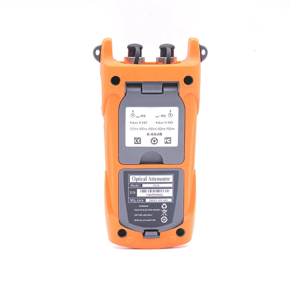
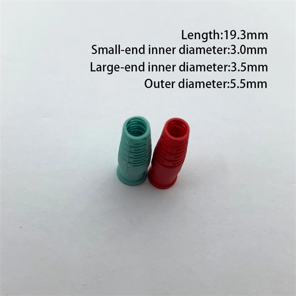
Product Features: Square protective box, suitable for skin cable and leather cable tight protection 6cm in length of skin heat shrink tube welding protection. A close connection between the leather cable and pigtail. Looking for specific info?. *In the era of high bandwidth, reliable fiber optic power equipment is particularly important. This handheld photometer can help check cable performance, calculate relative power loss, locate faults, and troubleshoot. *Measure the length of network cables, coaxial cables, and telephone cables. Able. Usually ships within 3 to 4 weeks Click here for details of availability. Able to test open, short, cross-connect, See more product details TABKER 4000667180167 3 x 2 x 1. Check each product page for other buying options. Price and other details may vary based on product size and color. Need help?. power across any given fiber. This document will serve as an overview of the major features and functions of the device and will ofer tips for trouble shooting com on issues in optical networks. If you are looking for a low cost device capable of saving and reporting take a look at the RP460 or. ments to the instrument's performance and functionality. The figures given in this manual ion of this manual to ensure the accuracy of its contents. However, should you have any questions or fi gistered users with a variety of information and services. Please allow us to serve you best by.
[PDF]

Optical fibers or fiber cables can be used for transmitting optical power from a source to some application. In their served areas will be power generating stations, alternative energy sources (solar, wind, geotherman, etc. ), substations for distribution and microgrids. These networks must be monitored and managed to ensure reliable power for the utility's customers. For monitoring and managing networks. Low voltage cables are mounted on poles in the "telecom space," well below power cables. Optical power ground wire (OPGW) is an electrical power ground with fiber optics in the center of the conductor. That conversion can be done with a photovoltaic cell. The Commission, on June 22, 1965, noting that the increasing demand for underground electric and communication facilities in California has brought about substantial increases in the construction of such facilities, and that it appeared it may be desirable, pursuant to Sections 761, 768 and 8056 of. One choice is optical power ground wire (OPGW). This conductive cable is run at the top of the tower or pole to be the ground conductor and protect the power cables from lightning. The fiber. While fiber optics is essential for internet service providers to deliver higher bandwidth and faster transmit speeds, there are also many crucial benefits of fiber optics in energy and power. Utility companies face various challenges as they work to deliver reliable energy to homes and industries.
[PDF]
Whether you're building a commercial setup or upgrading an industrial plant, proper cable tray installation ensures neat wiring, safe access, and easy maintenance. But before you lay the first tray or clamp down a single cable, you need a solid plan. This guide breaks. This method statement covers the site installation of the cable tray & ladders and the requirements of checks to be carried out. The Cable Tray system is installed in electrical rooms, plant rooms, and service corridors. This guide breaks down the process step by step. This process is integral to determining the optimal arrangement and configuration of cable trays, which are essential for routing and supporting electrical cables within buildings and. 1. 0 This method statement will serve as a minimum guideline to carry out the Cable Tray Installation activities for commercial buildings, plants and refineries in accordance with Project Drawings and Specifications. This document outlines the key requirements for cable tray layout, installation, and fireproofing in industrial and commercial environments. Route. Below is the detailed cable tray installation method statement not only for cable tray but also applicable for GI ladder and trunking for indoor and outdoor applications and in service rooms like pump rooms, electrical rooms and plant rooms etc. All materials intended for cable tray, ladder and.
[PDF]

To use a power meter for fiber optic testing, always clean connectors first with lint-free wipes or click-to-clean tools. Select the correct wavelength and set your reference. You measure optical power in dBm or insertion loss in dB. Consistent procedures ensure accuracy. Verify light travels from. The most basic fiber optic measurement is optical power from the end of a fiber. This measurement is the basis for loss measurements as well as the power from a source or presented at a receiver. Typically both transmitters and receivers have receptacles for fiber optic connectors, so measuring the. An optical power meter measures the strength of light traveling through a fiber optic cable, giving you a reading in dBm (decibels relative to one milliwatt). This article will guide you through the methods, instruments, and key considerations for measuring fiber. Fiber optic cabling is the high-performance core of today's datacom networks. As network speeds and bandwidth demands increase, fiber performance requirements have become more stringent. Fiber testing is more important than ever. An OPM uses a photodiode to generate an electrical current proportional to optical power.
[PDF]
Electric power distribution systems are designed to serve their customers with reliable and high-quality power. The most common distribution system consists of simple radial circuits (feeders) that can be ove.
[PDF]
We are a one-stop shop for top-notch Electrical Cable Tray in Brazil. Our cable trays are manufactured from robust materials and rigorously tested to ensure they can withstand even the most demanding environments. With 8,500 m² of built area, Eletropoll Trays offers to the market electrical ducts, profiles, beds, accessories, fasteners and support, busbars for lighting and related products. The Tray Unit has achieved excellent certifications. We, one of the top Electrical Cable Tray Manufacturers in Brazil, offer a wide. If you are searching for Cable Tray in Brazil, Brilltech Engineers Pvt. is a trusted brand that you can rely on. We have a well-equipped manufacturing unit with all the advanced resources to cater to your distinct requirements as per your industry preferences. Moreover, our focus on maintaining high quality and. EAE Electric started the production and use of busbar trunking systems in Turkey in the 1970s. Support systems can be manufactured with thicknesses from 2mm to 6mm with Pre-galvanized, Hot Dipped Galvanized, and Painted coatings in various options. EAE cable trays are produced on automatic. Chalfant Ladder Cable Tray Systems are ideal for indoor and outdoor cable management. They provide reliability, ease of installation, and cost savings both initially and long term. With multiple finishes available, we have the perfect ladder tray for any environment. screwless connections.
[PDF]
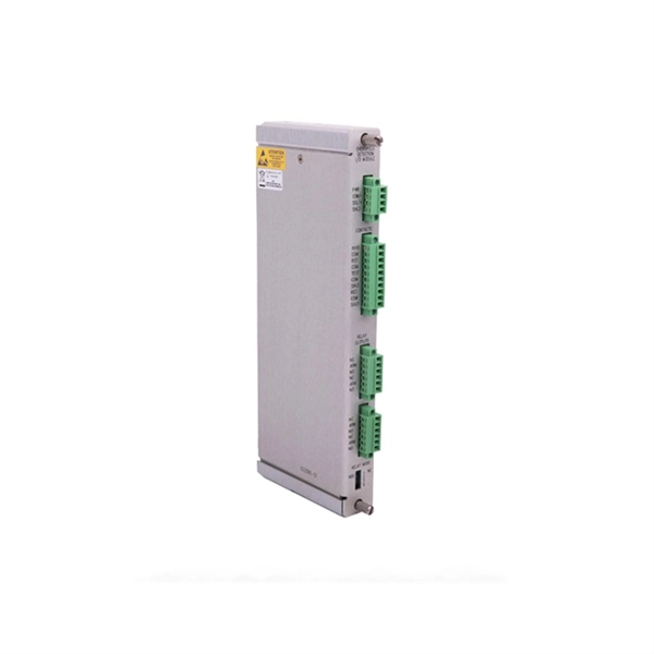
Integrated Power Services (IPS) is your power partner for operating reliability. We repair, rebuild to “like new” condition, and remanufacture electrical equipment. We also supply low- and medium-voltage circuit breakers, switchgear, transformers, and related parts, both new and obsolete. National. From sales to repair to field services, we support reliable energy solutions across clean and traditional power systems. Harnessing energy from clean and traditional sources, we deliver tailored solutions for reliable and efficient power generation systems. Whether it's electromechanical equipment. Integrated Power Supply provides a stable and reliable AC and DC power supplies against all AC mains variations or interruptions. Enhance safety in train operations (by avoiding blanking of signals). It consists of the following modules: The. Independent Power Setup: Critical instruments or instrumentation systems are equipped with dedicated uninterruptible power supplies (UPS). This ensures continuous power during unexpected outages in the main power grid, safeguarding data integrity and preventing equipment shutdown. For instance. At their base level, residential, commercial, and industrial automation complexes must incorporate a wide range of security, safety, and emergency communications systems for insurance requirements and local building codes, and to receive a certificate of occupancy.
[PDF]

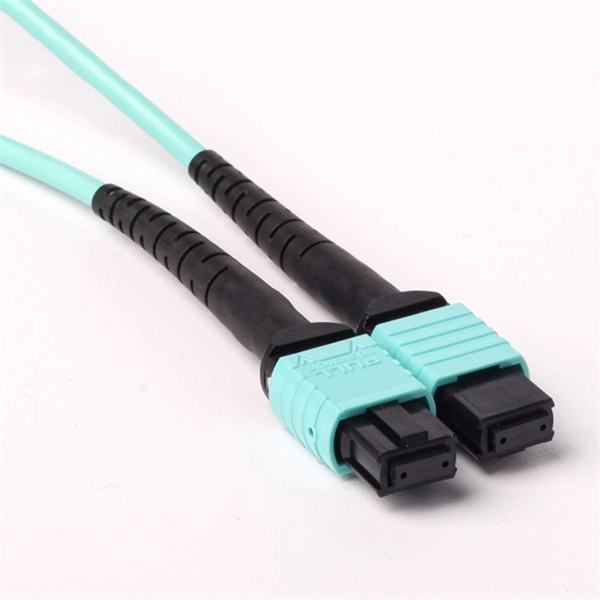
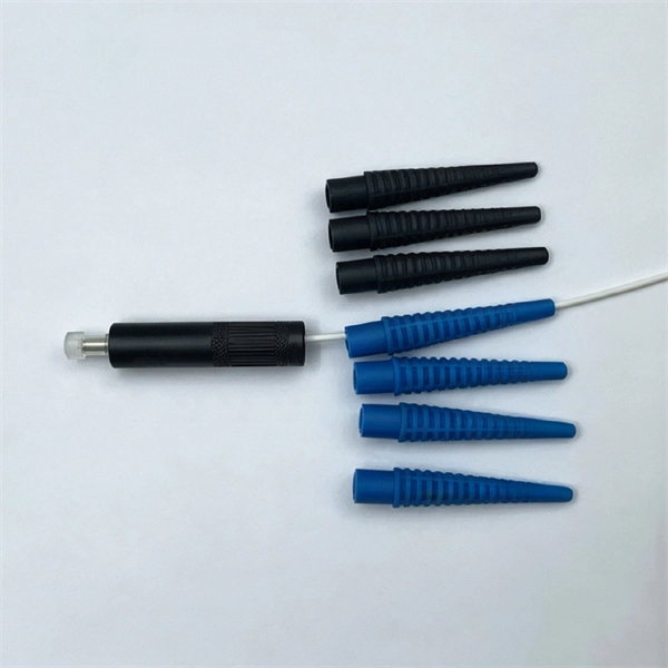
In short length cables a visual fault locator (VFL) can find where the cut is or find the bad connector at patch panels. For longer distance cables, the use of an OTDR is required. Once the fault is located, fusion splicers and splice-on connectors can be used to complete the repair. Fiber optic cables are the backbone of modern networks, delivering fast and reliable data transmission. Accidental cuts, breaks, or other damage can disrupt your network and cause costly downtime. With the right tools and techniques, you can efficiently repair damaged fiber cables and restore. Fiber optics offers advantages like EMI immunity and low attenuation (0. 2 dB/km), but it's fragile—susceptible to breaks, bends, and contamination. Repairs focus on restoring the light path with minimal signal loss (<0. A fusion. Visual inspection and specialized tools like OTDRs, OPMs, and VFLs are essential for identifying and locating physical damage or faults in fiber optic cables. Emergency restoration planning involves implementing backup power solutions, network redundancy planning, and strategies for prompt. Fiber optic cables are critical components of modern communication networks, transmitting vast amounts of data at lightning speeds.
[PDF]
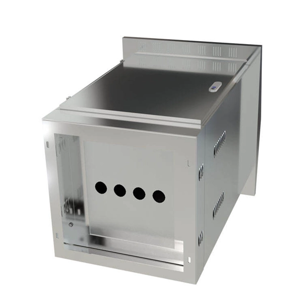
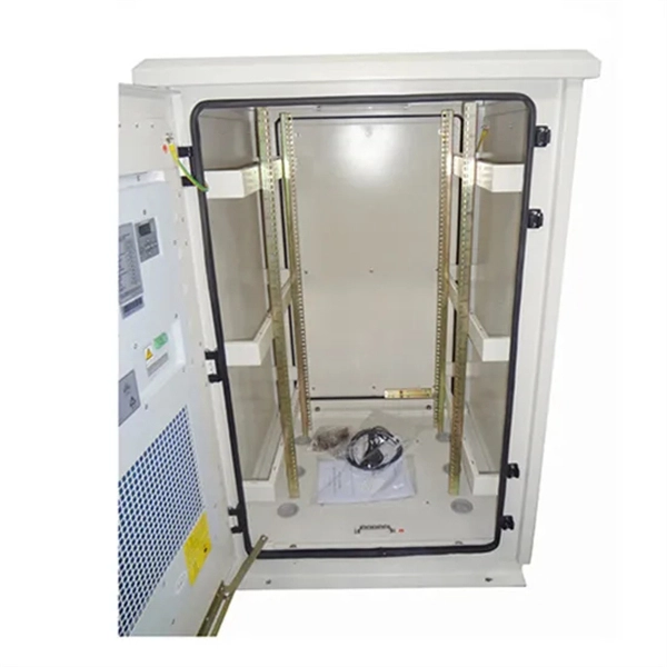
Papua New Guinea's rugged terrain and growing energy demands make outdoor energy storage cabinets a critical component for reliable power distribution. This article explores the unique requirements, technological advancements, and trusted manufacturers serving this dynamic market. This article explores how customized lithium battery systems address remote electrification, mining operations, and renewable integration while boosting sustainability. However, high temperatures and humidity pose challenges for battery longevity. This is where liquid cooling plate technology becomes. Summary: Papua New Guinea's growing energy demands require tailored battery storage systems to support renewable integration, rural electrification, and industrial growth. This article explores how customized energy storage solutions address local challenges, backed by case studies and industry. The project encompasses the construction of a solar and battery energy storage system (BESS) minigrid to be built on the island of Buka, within the Bougainville region. It will address the electricity needs of the region, which relies heavily on diesel generators. The deadline for applications is. Designed for remote locations, it integrates solar controllers, inverters, and lithium battery packs to ensure stable and continuous power for telecom equipment, surveillance systems, and off. Design engineers or buyers might want to check out various Lithium Battery Storage Cabinet factory &.
[PDF]
From the transformer, power goes to the busbar that can split the distribution power off in multiple directions. The bus distributes power to distribution lines, which fan out to customers.OverviewElectric power distribution is the final stage in the. Electricity is carried from the to individual consumers. Distribution connect to the transmission system an. Electric power distribution become necessary only in the 1880s, when electricity started being generated at. Until then, electricity was usually generated where it was used. The first power-distri. Electric power begins at a generating station, where the potential difference can be as high as 33,000 volts. AC is usually used. Users of large amounts of DC power such as some,. Primary distribution voltages range from 4 kV to 35 kV phase-to-phase (2.4 kV to 20 kV phase-to-neutral) Only large consumers are fed directly from distribution voltages; most utility customers are connected to a transformer.
[PDF]
Housing Integrity: Cracked, melted, or physically broken outer casings. Electrical Failure: Severe internal burn marks or "fried" traces that prevent a safe rebuild. Completeness: Units that have been scavenged for internal parts or are missing proprietary hardware. This document describes how to identify, isolate, and troubleshoot symptoms of hardware failures on Catalyst 9600 Supervisors and Line Cards. There are no specific requirements for this document. The information in this. If the switch has rebooted unexpectedly, you can follow the steps to troubleshoot the hardware. If your core looks different. This topic covers the steps for troubleshooting bootup, crash, network, software, and audio issues related to the Q-SYS Core 110f processor and Cinema Core 110c processor. It details what information to collect post-event to help identify the root cause. Requirements and Components Used Requirements: None specific to hardware/software versions. Lab. Hardware faults on CE switches include power supply faults, fan faults, card power-on failures, unexpected card restarts, abnormal optical module status, and abnormal interface status. The following information helps you quickly locate hardware faults. Common Causes of Power Supply Faults Common.
[PDF]

Key finding: This paper develops analytical models and design procedures of ultra-wideband Wilkinson power dividers using linearly tapered transmission lines (TTLs) which provide size reduction and broadband performance. Read more. Power dividers are the passive electronic equipment used for splitting the power. They are now being employed in a variety of communications applications such as telephonic, antennas configurations, mobile connectivity, internet technology, & optics, etc. They come up with very low loss, operate at. RF and microwave power splitters and dividers create two copies of the same signal, while ideally preventing crosstalk between the outputs. Doing this with minimal loss while maintaining signal integrity is a challenge. In this article we explain how power splitters work and what the tradeoffs are. The rise of wireless connectivity requirements for applications such as Internet of Things (IoT), cellular, and automotive electronics is resulting in systems that are increasingly using RF signals, components, and subsystems. Often, designers need to direct these signals to more than a single. A power divider is a passive electronic device used in radio frequency (RF) and microwave applications to split an input signal into multiple output signals with equal or specified power levels, while maintaining impedance matching to minimize signal reflection and loss. How can power dividers.
[PDF]
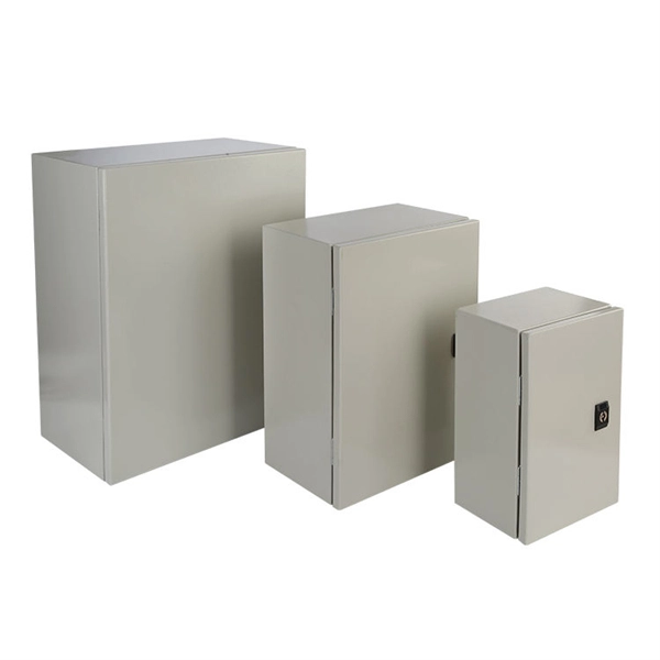
This AutoCAD DWG file includes a complete Single Line Diagram (SLD) of a Distribution Board, showing circuit breakers, wiring connections, and load distribution for lighting, power, and mechanical systems. Knowledge of the basic electrical power distribution system and its components will help the operator understand the importance of electrical power distribution systems. Failure-free power e. Overlapping protective zones a. Protective relays A single, or one-line. A power distribution box (also called PDU or distro) directs electricity from a main source to multiple circuits. It acts like a hub or traffic controller, managing power flow to different areas or devices. Key components include circuit breakers, fuses, bus bars, and internal wiring for safety and. Check electrical parameters: First understand the basic electrical parameters of Distribution box so that you can have a general understanding of the capacity and performance of the distribution box. Analyze the incoming line part: Determine the incoming line source of the distribution box and. ndards and conformity assessment activities in the United States. ANSI facilitates and promotes voluntary consensus standar rty or economic loss due to fire, electrical and related hazards. Now, let's look at how consumers use electrical power. What is a Electrical Power Distribution System? 1. Power supply is received from LT panel and distributed to the outgoing feeders for utilization.
[PDF]
From the transformer, power goes to the busbar that can split the distribution power off in multiple directions. The bus distributes power to distribution lines, which fan out to customers.OverviewElectric power distribution is the final stage in the. Electricity is carried from the to individual consumers. Distribution connect to the transmission system an. Electric power distribution become necessary only in the 1880s, when electricity started being generated at. Until then, electricity was usually generated where it was used. The first power-distri. Electric power begins at a generating station, where the potential difference can be as high as 33,000 volts. AC is usually used. Users of large amounts of DC power such as some,. Primary distribution voltages range from 4 kV to 35 kV phase-to-phase (2.4 kV to 20 kV phase-to-neutral) Only large consumers are fed directly from distribution voltages; most utility customers are connected to a transformer.
[PDF]