Featuring SC UPC connectors on both ends, it delivers low insertion loss and stable signal transmission. Its simplex structure and durable cable jacket make it suitable for a wide range of fiber optic installations. The SC/APC pre-polished fast connector comes pre-adjusted from the factory, with field-installable connectors that completely eliminate the need for hand polishing in the field. Proven mechanical splicing technology ensures precise fiber alignment, a factory-prepared fiber end, and a combination of. Technovate International Pvt. Ltd was established in 2017 with an objective to provide end-to-end fiber optic products and solutions to Internet Service Providers (ISPs) and Cable TV Operators in Nepal; and also supplying telecommunication equipment. We mostly import goods directly from our partner. Nepal - Shop for Best Online at Daraz. np Wide Variety of optic fiber sc connector. Great Prices, Even Better Service. 0mm Simplex is a high-quality fiber optic patch cable designed for reliable connectivity in telecommunications and networking applications.
[PDF]
In 5G fronthaul and backhaul networks, Small Form-factor Pluggable (SFP) modules are often the bridge between optical network elements and fiber paths. Clean, well-maintained fiber connectors are critical for maintaining low insertion loss and minimizing reflected power. In practice, dirty or. This article explores the wide range of fiber optic connector types, from legacy SC and ST to modern MPO/MTP and VSFF designs. Learn how each connector works, where it's used, and how to choose the right option for today's high-density, high-speed networks. Fiber optic connectors may look small. Fiber optic connectors are mechanical devices that join optical fibers with minimal signal loss, enabling high-speed data transmission. Key performance metrics include: Insertion Loss: ≤0. The performance of these networks heavily depends on the quality of optical connectors and splicing techniques used during installation and maintenance. They link fiber optic cables, allowing data to move quickly with minimal loss.
[PDF]

The main components of a splice box are the splice cassette that picks up the fibers and their reserves, and the front panel which contains different connectors for transmitting signals via copper or fiber optic cables. A splice box (also known as splice distributor) is a housing in which fiber optic cables begin or end. Fiber optics are fanned out in splice boxes that are situated at the end of fiber optic transmission paths. It typically consists of two parts: an outer housing and an internal structure. In this response, we will focus on the. The FSB series of indoor wall mount enclosures are designed for centralized splice-only applications. These boxes are well suited as optical cable splice collection points for DAS (Distributed Antenna Systems), MTU (Multi-Tenant Unit) commercial business applications, and MDU (Multi-Dwelling Unit). Fiber optic splice closures permanently connect two fiber optic cables together and have a splice that protects the components. The optical cable connection part, that is, the optical cable joint, is the part that protects the connection between two or more optical cables by the optical cable. Splicing refers to the permanent connection of two optical fibers to form a continuous optical connection.
[PDF]

Optical connectors are the physical interface that links an optical device to a fiber optic cable. Fiber optics are used in many applications, including medical imaging, automotive, military, industrial, and commercial (e., telecommunications). Each of these. Many people ask the same question: Can you use a fiber optic cable with an RJ45 port? The short answer is no - RJ45 connectors are designed for electrical Ethernet signals, while fiber optics transmit light pulses through glass or plastic. However, modern networks often combine both technologies. An optical fiber connector is a device used to link optical fibers, facilitating the efficient transmission of light signals. An optical fiber connector enables quicker connection and disconnection than splicing. They come in various types like SC, LC, ST, and MTP, each designed for specific. Proper connection of fiber optic cables is essential to harness these benefits fully, as even minor errors can lead to significant performance issues like signal loss. This article will guide you through the necessary tools, materials, and methods on how to connect fiber optic cables effectively. Most SFP fiber optic modules use LC connectors, while SC connectors are mainly found in legacy networks and MPO/MTP connectors are used for high-density cabling rather than directly on standard SFP modules. FC FO LC connectors for fiber optic.
[PDF]
The communication system of fiber optics is well understood by studying the parts and sections of it. The major elements of an optical fiber communication system are shown in the following figure. The ba.
[PDF]

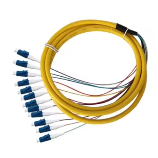
Fiber optic pigtails are short, single, or multi-strand pieces of optical fiber cables with a connector on one end and exposed fiber on the other end. They are typically used to terminate fiber optic cables and connect them to patch panels, equipment, or other termination points. Fiber pigtails are simple in appearance, yet essential in function. Despite this ubiquity, they remain a source of confusion for procurement teams and junior installers alike—especially when it comes to connector type selection, polish type, and the tradeoffs between mechanical. Fiber Optic Pigtails, also known as pigtailed fibers, consist of an optical fiber connector and a section of optical cable. Characterized by having an optical fiber connector on one end and a bare fiber end on the other, they are primarily used to connect optical transceivers or other optical. A Fiber Optic Pigtail Complete Guide: As per types, connectors, and applications. In such contemporary fiber optic communication systems, low-loss, and connectivities, which have reliability, are crucial for not only maintaining high-speed but also high-quality data transmission. It is usually suitable for field termination using a mechanical or fusion splicer. Compared with quick termination or epoxy and polish connections placed on the field.
[PDF]

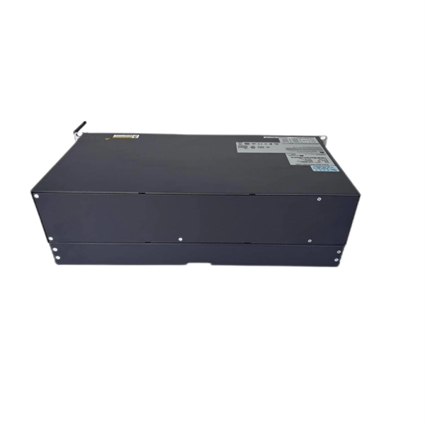
Arduino-Powered Data Transmission with Fiber Optics Welcome to our video tutorial on optical communication with Arduino, designed to be easy t. more. They consist of a transmitter on one end of a fiber and a receiver on the other end. Most systems use a "transceiver" which includes both transmission and. I'm going to use HFBR 1414 fiber optic transmitter module which is manufactured by Broadcom. It is a low-cost high-power transmitter that is designed for use in industrial power generation, power distribution, medical transportation and gaming applications. Internally, the optical fiber consists of a highly reflective central core, which acts like a light guide. Media converters are special fiber optic transceivers used to convert from one type of cable (the media) to another, typically from copper cables to fiber optics, although some media converters will convert from one fiber type to another, e. multimode to singlemode. The FOA Guide has a page about. A fiber optic transceiver (also called an optical transceiver) is a compact module that both transmits and receives data signals through optical fibers. It serves a dual purpose — transmitting electrical signals as light pulses and receiving light pulses to convert them back into electrical form.
[PDF]

Fusion splicing is the process of fusing or welding two fibers together usually by an electric arc. Fusion splicing is the most widely used method of splicing as it provides for the lowest loss and least reflectance, as well as providing the strongest and most reliable joint between. This guide reveals the secrets to fusion splicing with little fluff—just proven, straightforward techniques refined from years of work in the field. The goal is to fuse the two fibers together in such a way that light passing through the fibers is not scattered or reflected back by the splice, and so that the splice and the region surrounding it are almost as strong as the. A fusion splicer is a specialized tool used in fiber optic networks to join two fiber optic cables together permanently. This process creates a strong and reliable connection that can withstand. Splicing fiber optic cable is an extremely important phase for making dependable, high-speed communication infrastructures. Fusion splicing stands out as a superior technique for joining optical fibers, offering a seamless, low-loss connection that is crucial for reliable fiber optic networks. Let's explore the fundamentals of mechanical and fusion.
[PDF]

Since the earliest days of fiber optics, multimode cables have typically been color‑coded orange, black, or gray, while single‑mode cables are marked in yellow. For example, cable jacket color typically defines the fiber type, and can differ based on mode and performance level. These colors are typically chosen by industry standards bodies. However, there are some non-standardized colors and inconsistencies that you should be aware of. However, with the introduction of metallic connectors like FC and ST—whose bodies are difficult to color‑code—colored strain relief boots. Multimode fiber (MMF) is a kind of optical fiber mostly used in communication over short distances, for example, inside a building or for the campus. Multimode fiber optic cable has a larger core, typically 50 or 62. 5 microns that enables multiple light modes to be propagated. Because of this, more. Originally developed by the Electronic Industries Alliance (EIA) and the Telecommunications Industry Association (TIA), the TIA-598-D standard (formerly EIA/TIA-598) remains the most recognized color-coding system for optical fibers worldwide. On the right, the yellow patchcord indicates singlemode fiber and the blue connector means it is a regular PC polished connector, If it were an APC connector, it would be green. Perhaps nothing is.
[PDF]

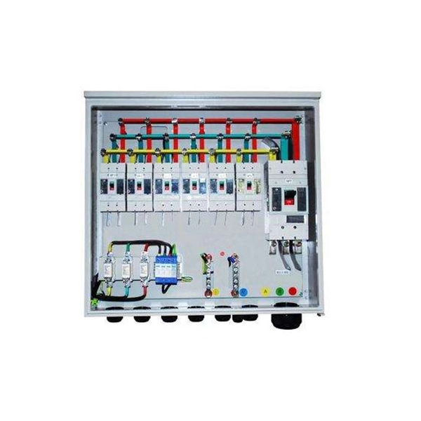
The box is typically composed of several parts, including the enclosure, the splitter module, and the connectors. An optical cable split fiber box is a device used in fiber optic communication networks to split the signal from one input into multiple outputs, allowing multiple devices to be connected to a single fiber optic cable. This provides users with a dependable and high-speed network service and little to no wait times. There is no need for an FDB if there is no. In modern FTTH (Fiber to the Home) and optical communication networks, three types of fiber distribution products are widely used: Splitter Distribution Box, ODF (Optical Distribution Frame), and Fiber Terminal Box. Although they all belong to the optical distribution and management system, their. A fiber optic splitter is a passive optical component that divides a single incoming optical signal into two or more outgoing signals, or combines multiple incoming signals into one. It can divide the input optical signal into multiple output optical signals to meet the fiber optic access needs of multiple terminal devices. This type of device plays an important role in passive. In this kind of fiber cabinet, the backbone fiber optic cable usually does not connect to optical splitters. However, in some metropolitan area, the backbone fiber cable will.
[PDF]
Stripping and preparing fibre optic cables for termination is a critical step in the installation and maintenance of fibre optic networks. Properly stripping the cable and preparing the fibre ends ensures a clean and secure connection, leading to optimal signal transmission and. If the fiber cracks in a cable assembly, the connection is weakened or lost. Your cable assembly house could face repairing or replacing connectors in the field, which could be exceedingly costly for your company. This article offers multiple tips and best-practice techniques to implement Above is. Once the fiber is cut, the cable moves to a new step of the assembly line, the preparation of the fiber for connectorization. As the phase that comes before, preparing the fiber for connectorization is a part of the manufacturing process, that has some specifications to it. The cable gets to this. The fibers need to have connectors fitted before they can attach to other equipment. In order to terminate a Fiber Optic cable, the appropriate connector must be determined. Various. At the heart of any robust fiber optic network lies a crucial process: Preparing a fiber cable for termination of a connector or splice. When the connector is subjected to stress or temperature.
[PDF]

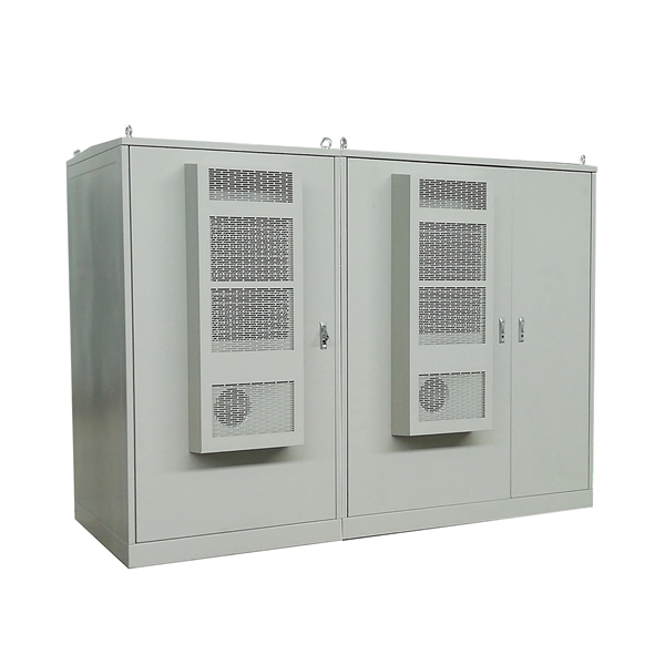
Here's a step-by-step guide to help you set up your fiber distribution box seamlessly: Before installing the fiber distribution box, ensure that your optical cables are properly prepared for connection. The optical fiber distribution box allows people to easily access the optical fibers in the box, and can well protect the optical fibers. In addition, the drawer structure also facilitates high-density wiring and good cable management. However, because optical fibers are fragile and can be easily. Keeping this page as a placeholder for now. Have any questions? Talk with us directly using LiveChat. Fix the rack to the ground with expansion bolts. Top installation: Dimensions of four connection holes on the top according to the. This instruction describes the installation of the Fiber Distribution Frame (FDF) manufactured by Corning Optical Communications. To order accessories that are purchased separately, contact Corning Optical Communications customer care for assistance. Read and understand this procedure (as well as. Optical fiber distribution frame is the wiring connection equipment between optical cable and optical communication equipment or between optical communication equipment. Distribution boxes are especially essential for FTTH networks, where they enable the efficient connection and management of optical fibers from a central.
[PDF]

Fiber optic cable can be run anywhere from 300 meters up to 80 kilometers (roughly 50 miles) depending on the cable type, transceiver used, and network standard. For most enterprise or data center applications using multimode fiber, the practical limit sits between 300 m and 550 m. Fiber optic cable transmission distance is determined by two primary physical factors that affect signal quality as light travels through the fiber medium. The greater the distance, the greater. Many factors decide the fiber cable distance, but the key factors include the below six aspects. Attenuation First is the attenuation of the optical fiber. OM2 extends this to 82 meters. OM1 fiber and OM2 fiber don't support these higher speeds. OM5 fiber matches OM4 at. For instance, without amplifiers, single-mode fiber can reach 50-60 miles and can support data rates of 1 Gbps or 10 Gbps. With amplifiers, such as Erbium-doped fiber amplifiers (EDFAs), the distance can be extended to 600 miles or more, and even further with additional amplifiers for long-haul.
[PDF]

Contrary to popular belief, fiber optic cables do not contain copper. Instead, they consist primarily of glass or plastic fibers that transmit data using light signals. These fibers are surrounded by protective coatings made of materials such as polymer or epoxy resin. Fiber optic cables are designed to provide high-speed, no-signal-loss, and EMI-free communication in telecommunication, powergrid, datacenter, broadband, and industrial applications. Each optical cable is constructed using a precise combination of optical fibers, strength members, buffer tubes. Fiber optic cables use pulses of light through ultra-pure glass or plastic fibers to carry information rather than electrical signals. Cladding: Lower refractive index layer reflecting light back into. You might wonder if there's copper inside fiber optic cables. It's not a yes-or-no answer. So, it's about knowing the different types. Its primary method of data transmission relies on light signals traveling through glass or plastic fibers, rendering copper conductors unnecessary for that purpose. Fiber optic cables have revolutionized data transmission. The two core material technologies used in almost all cables are fiber optic, and copper wiring.
[PDF]
The short answer is no - RJ45 connectors are designed for electrical Ethernet signals, while fiber optics transmit light pulses through glass or plastic. However, modern networks often combine both technologies. Fiber optic internet is a high-speed, reliable solution for modern connectivity, offering superior performance for both residential and enterprise networks. Fiber optic technology is a method of transmitting information from one point to another using light signals that are transmitted along thin, flexible fibers made of glass or plastic. It has become an essential component of our daily lives, providing fast and reliable communication over long. This tutorial explains the types of network cables used in computer networks in detail. Learn the specifications, standards, and features of the coaxial cable, twisted-pair cable, and fiber-optical cable. To connect two or more computers or networking devices in a network, network cables are used. Network cable connectors have various types and work for certain purposes. This article is a complete guide. It will give you an overview of these types and describe how they work. The fundamental difference between optical fiber and Ethernet cables is that optical fiber cables transmit data using light signals, while Ethernet cables transmit data using.
[PDF]
