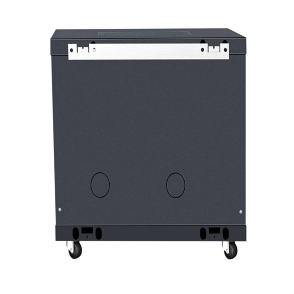
This template provides a structured approach to evaluating distribution boards, ensuring they meet safety and compliance standards. Using this checklist, you can identify potential issues early, enhance safety, and ensure regulatory compliance. It covers clear access and housekeeping, panel integrity and corrosion, proper mounting and canopy protection, junction box condition, covered switches and displays, and. Check for signs of corrosion or rust. Inspect for any physical damage to the enclosure. Ensure that all labels and warning signs are legible. Verify that the box is securely mounted and that there are no loose connections. Internal Inspection Open. The document is an electrical installations inspection checklist designed for weekly use, encompassing various safety and compliance criteria such as the condition of distribution boards (DBs), cables, and the grounding of electrical equipment. It includes checks for general condition, insulation, busbars, connections, auxiliary equipment, and circuit. Architects and Engineers Electrical Contractors Plumbing Contractors City and County Building Inspectors Manufacturers of Electrical Equipment Pacific Gas and Electric Company Employees 2022–2023 Edition (Supersedes All Previous Editions and Revisions) The Electric and Gas Service. An electrical distribution board inspection checklist is crucial for ensuring the safety and reliability of electrical systems.
[PDF]
Multimode Fiber Optic Receivers are devices designed to interpret information contained in optical signals transmitted through multimode fibers. These receivers convert the optical signals into electrical signals, allowing the data to be processed and utilized by electronic systems. Multimode Fiber. They convert electrical signals into optical signals for transmission over fiber-optic cables and reverse the process at the receiving end. Now, the term 'multimode' stems from the fact that these transceivers use multimode fiber (MMF) cables, which can carry multiple beams of light — or 'modes' —. Multi-mode optical fiber is a type of optical fiber mostly used for communication over short distances, such as within a building or on a campus. Multi-mode links can be used for data rates up to 800 Gbit/s. Most systems operate by transmitting in one direction on one fiber and in the reverse direction on another fiber for full duplex operation. For applications where long-haul transmission is unnecessary, multimode SFP modules offer a practical. They have a wider core (around 50 to 62. 5 micrometers), which enables multiple modes or light paths to coexist within the fiber, thus resulting in modal dispersion at shorter distances but reducing its efficacy over longer stretches. The choice between Single-Mode Fiber (SMF) and Multimode Fiber.
[PDF]
Single mode and multimode fiber optic cables are two different types of fiber optic cable aimed at different use cases. Single mode cables are typically made with a single strand of glass at their core, leading to a n.
[PDF]
We will look at how to interpret PLC LED status indicators for digital inputs and outputs and how to perform troubleshooting tests using a Digital Multimeter. This section includes the block diagram of the DI 16x24VDC ST module with the terminal assignments for a 1-wire connection. Information on wiring the BaseUnit can be found in the system manual ET 200SP distributed I/O system. The load group of the module must begin with a light-colored BaseUnit. How to wire real-world signals into the Logo's digital inputs to detect whether a machine is running. Covers stack lights, door sensors, relay contacts, and proximity switches — with a complete wire diagram and step-by-step instructions for both electrical engineers and IT teams. You have a Siemens. PLC and DCS control systems Wiring Diagrams for Digital Input (DI), Digital Output (DO), Analog Input (AI), and Analog Output (AO) signals. be responsible or liable for indirect or consequential damages resulting from the use or application of this equipment. The examples and diagrams in this manual are included solely for illustrative purposes. Because of the many variables and requirements. This manual contains information that is necessary to use the NX-series Digital I/O Unit. PLC programs rarely cause failures, so in this article, we'll assume that there are no program errors and that the fault originates in the.
[PDF]
ROSA refers to Receiver Optical Sub-Assembly, the primary function of which is to convert the optical signal transmitted from TOSA into electrical signal. ROSA contains a photodiode (PD), optical interface, metal and/or plastic housing, and electrical interface. This article will focus on the internals of the optical transceiver including the TOSA, ROSA and BOSA, and PCBA. Optical modules are devices used to connect network devices, transmit. As a key element in optical communication systems, optical transceivers serve as media between network devices to transmit and receive data. There has been lots of articles and guides on transceiver modules in the perspective of the package type while only a few of them cover the internal elements. Optical transceivers are essential components in modern telecommunications, facilitating data transfer between various network devices by converting electrical signals to optical signals and vice versa. The following section will focus on. An optical receiver is a device that converts light signals traveling through fiber optic cable back into electrical signals that electronic equipment can process.
[PDF]
In simple terms, Receiver Sensitivity is the minimum received optical power required at the input of a receiver for the system to achieve a specified performance level, typically defined by a maximum Bit Error Rate (BER). Think of it like listening to a distant radio station. The standards body governing the application sets this specified BER. For example, SONET specifies that the BER must be 10 -10 or better. Optical modules form the backbone of modern data center networks, enabling ultra-high-speed data transmission between servers, switches, and storage devices. In optical link design, the receiver performance parameters are like vital signs of the link, directly determining the reliability and. Receiver sensitivity shows the weakest signal your device can find. Good sensitivity gives stronger connections, even with weak signals. Always look at the dBm value in product details. A lower dBm means better receiver sensitivity. This helps you pick the best device. It denotes a module's capability to function in challenging environments and aids network operators in determining the system's maximum reach or link margin.
[PDF]
Find all you need for professionally buying optical fiber communication systems and devices: a comprehensive expert-curated directory of suppliers, scientific and technical background information, and an interactive AI-based tool with guidance for a structured decision process. T he MACOM PRISM-50D™MATP-05026D device is a 50G PAM4/NRZ PHY with integrated DSP and multiplexing functionality designed to enable single-wavelength 50G optical transceiver solutions. MACOM PRISM-50D™ is a highly integrated device offering low latency, low power, and a small foot print package. FIBERSTAMP 100G QSFP28 CLR4 optical transceiver are used for medium and long distance interconnection in data centers, complying with 100G CLR4 MSA specification and compatible with both 100G Ethernet and InfiniBand EDR transmission protocols. The product has a built-in pair of 4-channel CWDM MUX. GIGALIGHT 100G QSFP28 LR4 optical modules are used for long-distance transmission in the datacom or telecom field and are compliant with IEEE 802. 3ba 100GBASE-LR4 Ethernet transmission protocol, with optional dual-rate versions compatible with 100G Ethernet and OTN OTU4. The package contains a high-speed DFB laser chip, thermoelectric cooler, thermistor, optical isolator, and a rear-facet monitor. Contact Optilab for more information and pricing options. The Optilab DML-1550-PM-M is a directly modulated laser (DML) module with Polarization Maintaining fiber output at 1550 nm. You appear to be.
[PDF]
Discover the most common types and models of Direct Attach Cables (DACs), including 10G, 25G, 40G, 100G, 200G, and 400G. A Direct Attach Cable (DAC) is a factory-assembled high-speed copper cable with fixed connector “module-style” ends. It's widely used for short-reach links in data centers because it delivers low latency, simple deployment, and cost-efficient interconnects-especially for rack-level connectivity. These cables come pre-terminated with SFP (Small Form-factor Pluggable) or QSFP (Quad Small Form-factor Pluggable) connectors which simplify network setup. High-speed cable is a kind of low-cost short-distance connection solution to replace optical modules. Both of its ends have cable assemblies of a module, which are connected. Direct attach copper (DAC) cables are twinax copper assemblies with fixed transceiver-like ends. They deliver high bandwidth, low latency, and great density for top-of-rack (ToR), server-to-switch and switch-to-switch connections. This article summarizes the common DAC categories and. What is a Direct Attach Copper (DAC) Cable? Common Types And Uses Summary : Direct Attach Copper (DAC) cables provide fast, reliable, and cost-effective short-distance connections for data centers, enterprise networks, and top-of-rack setups. With passive and active variants, DAC cables offer.
[PDF]