Pricing (USD) Filter the results in the table by unit price based on your quantity. View All Products at Mouser Electronics. Mouser Electronics is an authorised electronic component distributor offering online ordering and no minimum orders. 71 billion by 2035 from USD 15. 8% from 2025 to 2035. There is an increasing need for busbars due to industrialization, strict government policies on energy use, and rising electricity costs. These factors compel. Market Forecast By Conductor (Copper, Aluminum), By Power Rating (Low, Medium, High Power), By End-User (Utilities, Commercial, Industrial, Residential, Industrial Chemicals & Petroleum, Metals & Mining, Manufacturing) And Competitive Landscape The busbar market in Israel encompasses a wide range. The Israeli market for copper ribbons and busbars for photovoltaic (PV) applications represents a critical and dynamic segment within the nation's broader renewable energy and high-tech industrial landscape. As of the 2026 analysis period, this market is characterized by its direct dependence on. Cybex Exim brings you latest and updated Trade Intelligence report of Busbars Import Data Under HS Code-741980909000 from regular updated Import shipment data of Israel Customs. Israel Import data is compiled on regular basis from all Israel ports. Power to the Board Busbar, 100A, 480 VAC, 56 Pin, 2-pole Gladitaor UL1077 protectors without auxiliary components.
[PDF]
Start by examining the plastic cover closely to identify any tabs or locking mechanisms that may be holding it in place. This robust enclosure houses either the main service disconnect or a sub-panel, acting as a control point for electricity distribution to the property or a dedicated outdoor system like a pool or workshop. Gaining access to the panel's interior is usually necessary for simple tasks like resetting a. Opening electrical boxes outside can be a tricky endeavor. Without the proper tools, knowledge, and safety measures, it can also be dangerous. However, with a few simple steps, you can open an outdoor electrical box safely and efficiently. This is how you can open them to have access to the plug-ins. Once you've loosened the. This guide will explore the steps and considerations for safely and effectively punching out a plastic electrical box. Ensure the wires are not powered before starting work. Flat-head screwdriver, electrical pliers, hammer, and a suitable meter or tester. Locate. Before you attempt to open an outdoor breaker box, it's crucial to prioritize your safety. Here is a set of guidelines to ensure you undertake this task without any hazards: Confirm power is disconnected to the unit by turning off the main breaker or disconnecting the main fuse.
[PDF]
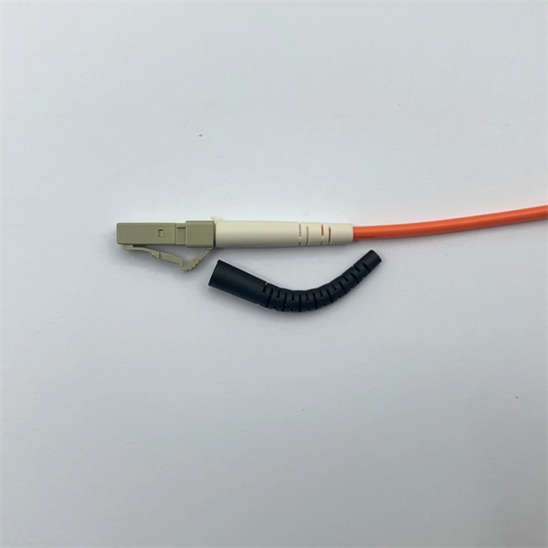
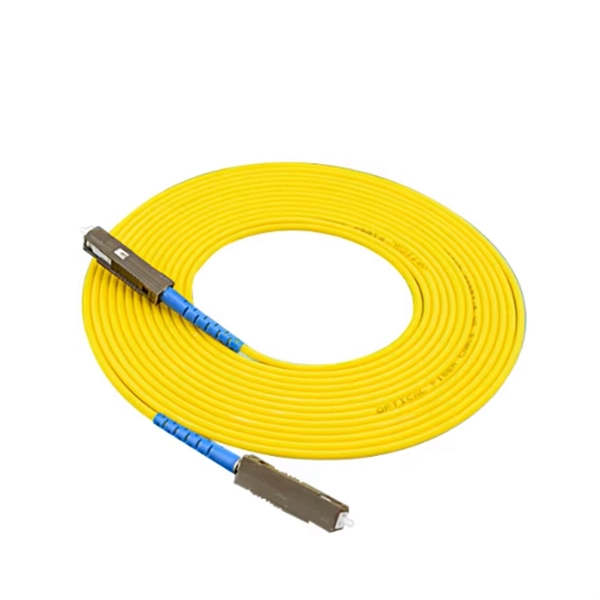
An optocoupler is a coupling device used to couple optical signals. It's primarily employed to combine and split signals in optical networks, and it's also referred to as a directional coupler. Image alt: Optocoupler-Optical coupler The figure above depicts a 2x2 coupler with two input ports and. It is widely used for coupling or splitting light waves through waveguides or fibers and can be availed in the form of either active or passive devices. The main difference between active and passive couplers is that the passive coupler redistributes the optical signal without converting optical. Optical couplers, essential components in the realm of fiber optics and telecommunications, stand at the forefront of enabling efficient, versatile, and reliable optical signal processing. In ophthalmic imaging; the coupler: A-Z > O > What Is an Optical Coupler? Share Provide a valuable. A coupler is an optical device that combines or splits optical signals. The basic principle of a coupler is to transfer optical power from one or more input ports to one or more output ports.
[PDF]
Fiber optic pressure sensors operate based on the principle of light modulation in optical fibers. When pressure is applied to the sensing element, it changes the properties of the fiber, such as the refractive index or the intensity of the light. These sensors are gaining popularity. Fiber-optic sensing (FOS) technology has emerged as a cutting-edge research focus in the sensor field due to its miniaturized structure, high sensitivity, and remarkable electromagnetic interference immunity. Compared with conventional sensing technologies, FOS demonstrates superior capabilities in. This article explains the structure, working principle, advantages, and disadvantages of Fiber Optic Pressure Sensors. Compared to traditional electronic pressure sensors, they offer advantages such as immunity to. Fiber optic pressure sensors are transforming how industries monitor and manage critical systems. Unlike traditional sensors, these devices use light to measure pressure changes, offering high accuracy, immunity to electromagnetic interference, and durability in harsh environments.
[PDF]
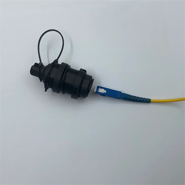
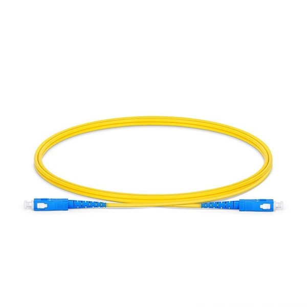
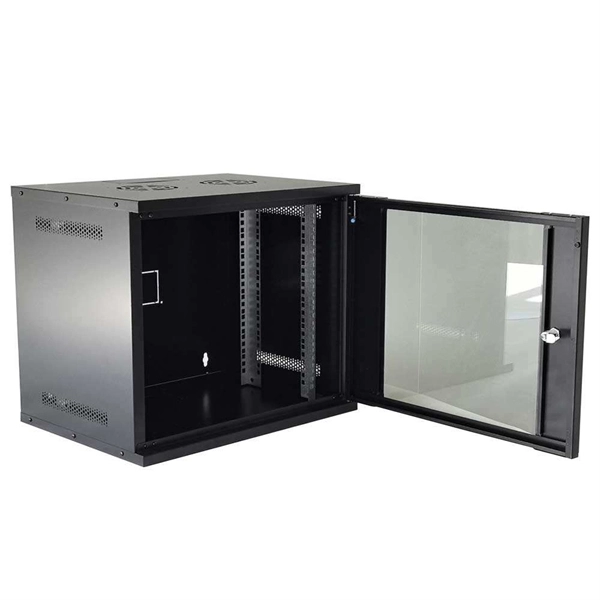
A fiber optic termination box is an enclosure designed to terminate incoming optical fiber cables and distribute optical signals to drop cables or patch cords. It integrates fiber splicing, adapter management, and cable protection in one compact unit. A fiber optic termination box, often called an optical distribution frame (ODF) or fiber patch panel, serves as the endpoint where incoming fibers connect to devices or. A fiber optic termination box is a core component in modern fiber optic networks, providing a secure and organized point for fiber termination, splicing, and distribution. It is widely deployed in FTTH, FTTB, and other access networks to ensure stable signal transmission from backbone cables to end. Fiber termination refers to the process of preparing the end of a fiber optic cable to connect to another fiber, a device, or a network. There are two primary. A Fiber Termination Box, also known as a Fiber Distribution Box, is a crucial component in fiber optic networks. It is a small enclosure that can house and protect the fiber optic cables, splices, and connectors. The fiber termination box. Choosing the right fiber optic terminal box is less about buzzwords and more about matching physics and field reality to your site: where the box will live, how many cores you need now and later, how technicians will access it, and what level of environmental and mechanical protection the network.
[PDF]

A FOSC is a protective enclosure designed to house, organize, and environmentally seal optical fiber splices, providing mechanical protection, water resistance, and easy re-entry for maintenance. At the core of this system's precision and reliability are Fiber Optic Splice Boxes—the unsung heroes that house and protect the delicate junctions where fiber cables are joined. The integrity of these enclosures is paramount to network performance. This guide optimizes the original text by delving. A splice box (also known as splice distributor) is a housing in which fiber optic cables begin or end. The main components of a splice box are the splice cassette that picks up the fibers and. Optical cable joint box The optical cable joint box permanently connects two optical cables together and has a joint part for protecting components. The optical cable connection part, that is, the optical cable joint, is the part that protects the connection between two or more optical cables by the optical cable. In the fast-evolving world of fiber optic networks, where FTTH connections surpass 2 billion globally and 5G/50G-PON deployments accelerate, one component quietly ensures long-term reliability: the Fiber Optic Splice Closure, commonly abbreviated as FOSC. Optical cable splice boxes protect the splicing parts of optical fibers from various hazards, such as water seepage due to adverse.
[PDF]
The AWGs are used to multiplex channels of several wavelengths onto a single optical fiber at the transmission end and are also used as demultiplexers to retrieve individual channels of different wavelengths at the receiving end of an optical communication network. Arrayed waveguide gratings (AWG) are commonly used as optical (de)multiplexers in wavelength division multiplexed (WDM) systems. These design of these devices are based on an. A 32-channel 50-GHz spaced arrayed-waveguide grating with our innovative configuration has been designed and fabricated. The performance of the device has been fully tested by using a tunable laser light source, optical power meter, and polarization controller. AWG has filtering characteristics and versatility, which can obtain a large number of wavelengths and channels, to realize the multiplexing and demultiplexing. The arrayed waveguide grating (AWG) is a planar versatile light-dispersion component with high accuracy, robustness, and design flexibility. It has become an attractive component not only for telecommunication (e., multiplexer or demulti-plexer)[2,3] but also for medical imaging,[4–6]. uide Grating Routers (WGRs). The acronym AWG, introduced by Takahashi , is the most frequently used name today and wi l also be used in this text. Together with Thin-Film Filters and Fibre Bragg Gratings, AWGs are the most important filter type applied in WDM networks, and with the advance of.
[PDF]
Cold aisle containment (CAC) is a proven data center cooling strategy that creates physical barriers around cold air supply zones, preventing contamination from hot exhaust air and eliminating the energy-wasting effects of air mixing. This approach transforms traditional hot aisle/cold aisle. Cold Aisle Containment isolates the cooled supply air from the cooling units within direct proximity of the air intake of critical equipment. An enormous amount of energy is used every day to maintain an acceptable intake temperature to the IT equipment. By isolating the cold aisle, containment reduces unintended mixing of cold supply air with hot exhaust air, maintaining uniform, predictable. The cold aisle layout is the most common starting point in data center design. Server racks are arranged in rows so that the fronts of the racks face each other, forming a corridor known as the cold aisle. A look at the science behind hot and cold containment aisles reveals that server racks stand in rows and alternate the way they face. One row faces forward so the server.
[PDF]
The optocoupler can be used in many different applications as an interface between low voltage digital, such as 3. 3V logic, or 24V control circuits and large mains power electronic devices. Thus protecting sensitive circuits (e., microcontrollers) from high-voltage supplies. Optocouplers, also known as opto-isolators, uses infrared light to transfer electrical signals between two electrically isolated circuits and are commonly classified by their photosensitive output device What is an Optocoupler? An optocoupler (also called an opto-isolator, photo-coupler, or optical. Optocouplers become specifically useful where an electrical signal is required to be sent across two circuit stages, but with an extreme degree of electrical isolation across the stages. Optocoupling devices work as logic level changeovers between two circuits, It has the ability to block noise. An opto-isolator (also called an optocoupler, photocoupler, or optical isolator) is an electronic component that transfers electrical signals between two isolated circuits by using light. Opto-isolators prevent high voltages from affecting the system receiving the signal.
[PDF]
A fiber optic termination box is an enclosure designed to terminate incoming optical fiber cables and distribute optical signals to drop cables or patch cords. It integrates fiber splicing, adapter management, and cable protection in one compact unit. It is widely deployed in FTTH, FTTB, and other access networks to ensure stable signal transmission from backbone cables to end. ■ What is a Fiber Access Terminal (FAT)? A Fiber Access Terminal (FAT), also known as a Fiber Access Terminal Box (ATB) or Fiber Distribution Terminal (FDT), is a key component found in optimized fiber optic access networks for FTTH implementations. It acts like the "central nervous system". Fiber termination boxes play a vital role in ensuring efficient and reliable fiber management in FTTH applications. By understanding the components, types, and differences between various fiber management devices, businesses can make informed decisions when deploying and maintaining their fiber. But what exactly is the purpose of a fiber optic terminal box, and why is it so crucial in the realm of optical communication? First and foremost, a fiber optic terminal box serves as a robust protective shield for fiber optic cables and their delicate connections. It offers higher reliability and more flexible deployment and configuration than traditional terminal boxes. It is usually installed on the wall in the user's room or on the rack in the telecom room, and.
[PDF]
Fiber Bragg grating (FBG) sensors have emerged as advanced tools for monitoring a wide range of physical parameters in various fields, including structural health, aerospace, biochemical, and environmental applications. A fiber Bragg grating (FBG) is a type of distributed Bragg reflector constructed in a short segment of optical fiber that reflects particular wavelengths of light and transmits all others. This is achieved by creating a periodic variation in the refractive index of the fiber core, which generates a. A Fiber Bragg Grating (FBG) sensor is a specialized device that uses light within a glass fiber to detect environmental changes. This review provides a comprehensive overview of FBG sensor technology. Fiber Bragg grating (FBG) optical sensors have emerged as a leading technology for distributed strain and temperature measurement. Their unique attributes—compactness, immunity to electromagnetic interference, and multiplexing capabilities—make them a compelling choice for industries ranging from. Optical sensors based on Fiber Bragg Gratings (FBG) are becoming increasingly popular.
[PDF]
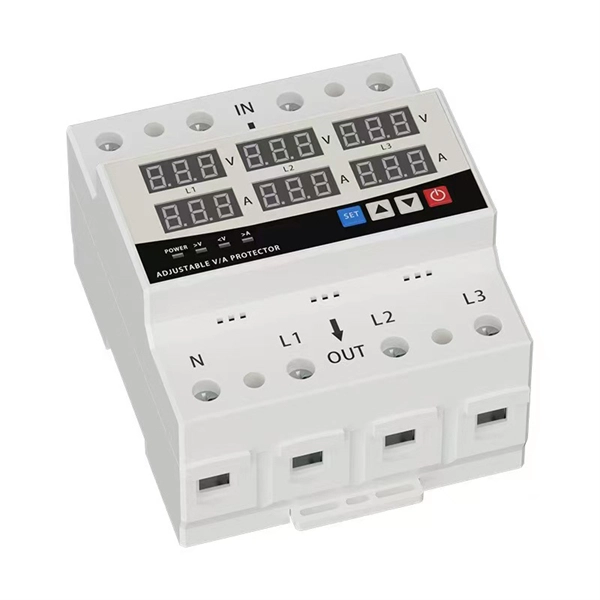
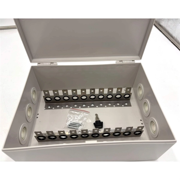
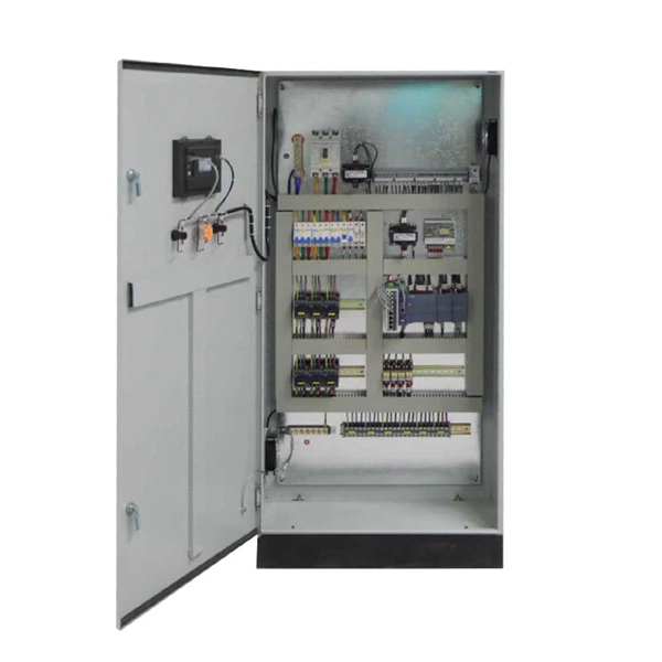
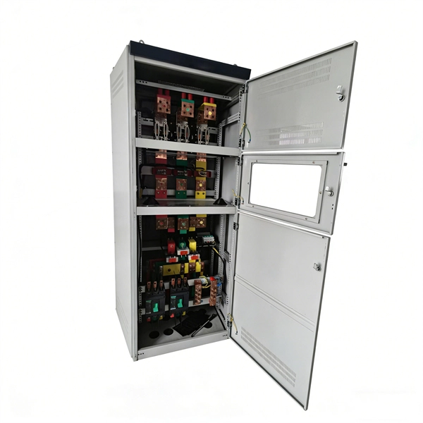
Residual current protection (RSD/RCCB/RCBO): Detects leakage current and cuts off power to reduce electric shock risk. Earthing connection: Ensures proper grounding to maintain safety and system stability. Many modern distribution boxes include a life-saving device called an Earth Leakage Circuit Breaker (ELCB) or Residual Current Device (RCD). It detects tiny imbalances in current that could be flowing through a person (electric shock) and cuts power in a fraction of a second. The Role of Material:. Metal Distribution Boxes: Made from steel or aluminum, these are used in places that require higher safety standards, such as fire-resistant buildings. Plastic Distribution Boxes: Constructed from materials like PVC or polycarbonate, these boxes are light and resist corrosion, making them suitable. These tools show where you can save electricity. Smart meters show detailed energy use. Monitors cut waste by improving power use. Efficient boxes reduce power loss in big buildings. It integrates power distribution, protection, and monitoring capabilities, and is responsible for distributing power to entire commercial or residential.
[PDF]
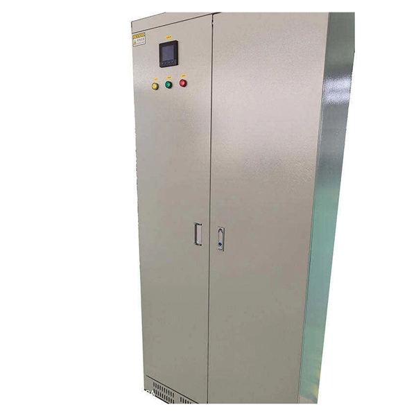
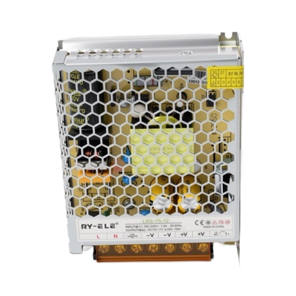
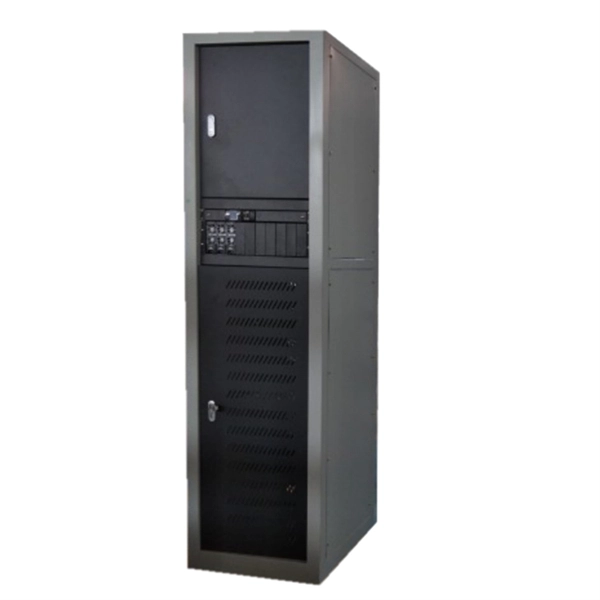
A power distribution unit (PDU) is a device fitted with multiple outputs designed to distribute electric power, especially to racks of computers and networking equipment located within a. Data centers face challenges in power protection and management solutions. This is why many data centers rely on PDU monitoring to improve efficiency, uptime, and growth. For data center applications, the power requi.
[PDF]
OPGW cable vibration dampers are essential devices designed to reduce aeolian vibration in optical ground wire cables. Whether spiral, Stockbridge 2 or clamp type, these dampers work by absorbing vibration energy, which prevents fretting fatigue and premature breakage of the cable. This article explores the importance of optical cable vibration dampers, their design and functionality, and. IEC describes the Stockbridge damper as a system consisting of a messenger cable with two masses at its ends and a clamp that supports them; this clamp is attached to the conductor or earthwire with the purpose of reduction of the aeolian vibration on the conductor. Sure enough, starting from a. All Rights Reserved | Privacy Policy | Sitemap Vibration Dampers - Conductor vibration induces a relative motion between the clamp and the inertia weights which causes flexure of the steel cable, resulting in dissipation of mechanical energy by friction between the strands of the damper cable. In. The non-slip type vibration damper we provided with particular weight and reasonable shape design,it can produce multi resonant frequencies and effective absorption the different frequencies of vibration. Adopting the helical structure form of installation, it have large adhesion area and evenly. The Spiral Vibration Damper is a motion control product used to dissipate aeolian vibration that may occur on cable spans. PLP transmission.
[PDF]
Busbars are essential components in electrical power systems, designed to distribute power efficiently within switchgear, panel boards, and distribution boards. Made from copper or aluminum, they serve as a central point where multiple circuits can connect, ensuring stable and. A bus bar (also spelled busbar) is a metallic strip or bar used in electrical power distribution to conduct electricity within a switchboard, distribution board, substation, or other electrical apparatus. Its primary role is to carry large current loads and connect multiple circuits together. In virtually every piece of electrical equipment—from switchgear and power distribution panels to EV battery packs and AI data centers—busbars play a vital, if often unseen, role. These components are the silent conductors of power, ensuring efficient energy distribution, reliability, and compact. Busbars (bus bars) are a type of electrical conductor that, compared to traditional cables, allow for the transmission of current in a safer and more flexible manner. They ensure efficient and effective energy distribution, successfully powering single- and three-phase devices and machines, and. Busbars offer a clean, efficient way to manage power distribution, simplifying complex wiring jobs and boosting reliability.
[PDF]