A 150 m launch/tail cord will work for fiber links of 2 km or less, typically found in enterprise networks. This document provides instructions for the fiber cable technician to properly perform fiber cable preparations, rout-ings, splicing, terminations and connections within a Charles Industries' Fiber Distribution Point (CFDP2) EL24 Pedlock pedestal with a 10” dome. This model, shown in Figure 1. A: The fiber type of launch and tail cords must match the fiber type used in the fiber link under test. Q: How long should a launch or tail cord (launch or receive cable) be? The particular model OTDR you are using. Pigtails are available in various fiber types, such as single-mode or multi-mode, and connector types, including SC, LC, ST, or FC. These components are often left dangling, unused, or improperly labeled, and can be found coiled inside fiber distribution panels. The most efficient way to terminate a fiber run is by using a pigtail.
[PDF]
A beam splitter or beamsplitter is an optical device that splits a beam of light into a transmitted and a reflected beam. It is a crucial part of many optical experimental and measurement systems, such as interferometers, also finding widespread application in fibre optic telecommunications. DesignsIn its most common form, a cube, a beam splitter is made from two triangular glass which are glued together at their base using polyester,, or urethane-based adhesives. (Before these synthetic,. Beam splitters are sometimes used to recombine beams of light, as in a. In this case there are two incoming beams, and potentially two outgoing beams. But the amplitudes. For beam splitters with two incoming beams, using a classical, lossless beam splitter with Ea and Eb each incident at one of the inputs, the two output fields Ec and Ed are linearly related to the inputs thro.
[PDF]
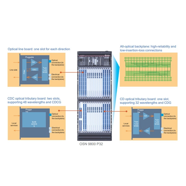
If you encounter any of these issues, check the optical connector for damage or dirt, inspect the fiber optic patch cord, ensure the optical module is correctly installed, and check the device settings for compatibility. Subsequently, the driver semiconductor laser (LD) or light-emitting diode (LED) emits modulated optical signals at the corresponding rate. After transmission through the optical fiber, the receiving interface converts the optical signals into electrical signals using a photodetector diode and. An optical module is a typically hot-pluggable optical transceiver used in high-bandwidth data communications applications. Optical modules typically have an electrical interface on the side that connects to the inside of the system and an optical interface on the side that connects to the outside. The Transmitter Optical Sub Assembly (TOSA) is responsible for the emission of light. Its primary function entails converting electrical signals into optical signals.
[PDF]
Solid Green: The ONT is powered on and functioning normally. What to check: Make sure the power cable is securely plugged into both the ONT and a working wall outlet. If you're using a power strip, check that it's turned on. Learn what each light on your fiber equipment means—from power and fiber signal to Ethernet and phone service—and how to quickly troubleshoot issues. This light shows whether your ONT is getting power. No Light: The ONT is not receiving. The Optical Network Terminal (ONT) is a crucial device in modern telecommunications, serving as the interface between your home network and the fiber-optic internet connection provided by your Internet Service Provider (ISP). The ONT has a series of lights that indicate its status and any potential issues. In this article, we will delve into. Power down for 15mins then power back on and wait 3mins for the lights to settle Power connector has come loose. Problem with the plug socket. Optical: This should be a solid green at all times (If the power light is off, this will also. This guide is designed to offer an explanation on how to troubleshoot issues with a CityFibre ONT (Optical Network Terminal). For more help topics, please visit the main Support Page. If you would like details on Freeola Broadband tariffs using the CityFibre Network, please visit our Broadband. You can use the status lights on your optical network terminal (ONT) to help find and fix internet issues. An ONT may also be called a Service box.
[PDF]

This guide on how to fix router red light, will walk you through the common reasons behind the red light and provide step-by-step solutions to bring your router back online. A red light on your router can be a source of frustration and confusion. It often indicates that something is wrong with your internet connection or the device itself. Fortunately, diagnosing and resolving these issues doesn't have to be complicated. You might feel like you're staring into the abyss of digital darkness, wondering what went wrong. But don't despair! This guide will walk you through the most common causes of router. Experiencing a solid red broadband light on your router can be frustrating and indicates a disruption in your internet connection. Understanding the possible causes and fixes for this issue is crucial to getting your connection back on track. Here are some steps you can take. The following article will explain why the Internet is light red and what you need to do to fix it. What does it mean by Internet Light Red On Router? Our router's lights are.
[PDF]
When encoding diffractive optical elements (DOE) onto a spatial light modulator (SLM), the diffraction efficiency can be reduced because of the pixel nature of the SLM. These effects have been studied previousl.
[PDF]
Lighting Control System | Smart Lighting Wiring Setup | Full Guide In this video, you will learn how to connect and install a Lighting Control System step-by-step. This guide covers wiring setup, switch modules, dimming control, sensor setup and panel . as a guide for proper and reliable installation. The mounting location should e selected and prepared based on the application. All electrical wiring and mounting hardware (i. ) should be prepared with consideration of the requirements o cuit breaker before. Intelligent Lighting Controls' installation guides provide detailed instructions on how to install all of our solutions. The Lightolier Controls Optio Lighting Control Panels are high-performance, wall mounted lighting control panels which offer a wide range of dimming and relay modules to accommodate any lighting control application.
[PDF]

This report describes a set of five field evaluations conducted by Pacific Northwest National Laboratory (PNNL) and DesignLights Consortium for U. Department of Energy, between November 2015 and September 2017, to demonstrate the potential energy-savings capability of advanced . Lighting systems define the difference between a toy grade machine and a professional-grade scale crawler. Choosing the right controller dictates how that light behaves, moving beyond simple on-off switches into the realm of true scale realism. Integrating these systems transforms a static rig into. What Defines a Great Lighting Control System in 2025? 1. Lutron (Vive & Quantum): The Scalable Market Leader 2. DALI (Digital Addressable Lighting Interface): The Open Protocol Standard 3. Crestron: The King of High-End Integration 4. Casambi: The Leader in Bluetooth Mesh Wireless Control 5. PoE. These systems provide a consolidated method for managing all of your home's lights using a single app or device. However, choosing from the wide range of available options might be challenging. To assist you in making a wise choice, we have put together a guide to the top home lighting control. re being properly set up and tested for the Program Administrators (PAs). These criteria will ease the decision-making around the appropriate savings factors and incentive levels that projects can claim. By combining technical parameters with hands-on project experience, it supports designers.
[PDF]

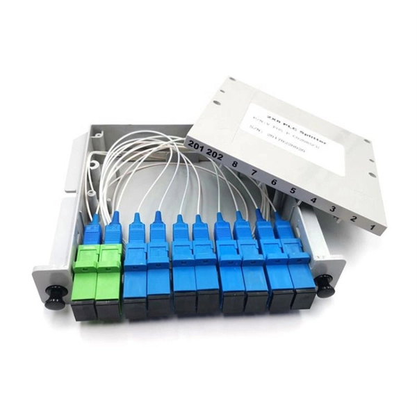
A fiber-optic splitter, also known as a beam splitter, is based on a quartz substrate of an integrated waveguide optical power distribution device, similar to a coaxial cable transmission system. The optical network system uses an optical signal coupled to the branch distribution. The fiber optic. In the backbone of modern Fiber-to-the-Home (FTTH) networks, optical splitters serve as the unsung heroes that enable cost-efficient connectivity for millions of subscribers. By dividing a single optical signal from a central Optical Line Terminal (OLT) into multiple outputs for Optical Network. Optical splitter, also called optical beam splitter, is an integrated waveguide optical power distribution device that can split an input optical signal into two or more output optical signals, and the optical input power is evenly distributed on all output ports. For example, an optical splitter. The answer lies in a small device. We call it an Optical Splitter. This device is the heart of Passive Optical Networks (PON). It allows service providers to save money. It helps them distribute bandwidth efficiently. In this article, we explain the definition, working principles, types, and. An optical splitter is a device that divides light transmission in a network into multiple output ends. It plays a crucial role in facilitating network interconnections.
[PDF]

The FLS-140 is the easiest way to identify optical fibers from end to end and locate polished connector endfaces. Its red laser shines through most yellow-jacketed optical fibers to help you pinpoint breaks, bends, faulty connectors, splices and other causes of signal loss. A Visible Fault Identifier (VFI), also referred to as a Visual Fault Locator (VFL), is an essential tool for fiber installation and maintenance technicians. AFL's compact VFI4 injects high-powered red-laser light to provide exceptional brightness and range for locating defects in single-mode and. The B5 Rechargeable Red Light Pen is a professional 650nm visual fault locator designed for fiber optic network maintenance, installation, and troubleshooting. Its advanced rotary automatic lift laser head ensures smooth operation, while the integrated LED lighting improves visibility in low-light. Whether installing or troubleshooting, the Visual Fault Locator (VFL) is an essential tool that quickly and easily locates problem areas in fiber cables. By pinpointing the exact location of fiber damage, technicians can diagnose, troubleshoot, and fix the problem efficiently. The VFL is also used. The state, throughput, and identification of an optical fiber can be easily checked with fiber testers by coupling highly visible laser light into the optical fiber. A high intensity visible red laser beam is precision-coupled.
[PDF]

The core measurement procedure follows five steps: Turn on the meter and let it warm up. Most meters need a brief stabilization period before readings are reliable. Check your model's manual, but a minute or two is typical. Set the wavelength to match your light source. Fiber loss is the difference between the power when light is coupled from the transmitting end to the fiber and the power when the light reaches the receiving end. Generally speaking, when measuring the. An optical power meter measures the strength of light traveling through a fiber optic cable, giving you a reading in dBm (decibels relative to one milliwatt). The basic process is straightforward: turn the meter on, set it to the correct wavelength, clean your connectors, plug in, and read the. A power meter and light source are essential test tools that work in tandem to measure fiber optic cable loss and evaluate the quality of optical links. They provide the data necessary to quantify signal loss and pinpoint issues that could impact network performance. Here's how they work: A power. You measure optical power in dBm or insertion loss in dB. Verify light travels from transmitter to receiver. We'll give you the basic information you need and provide some printable references.
[PDF]

Average Optical Power: How bright the light is (measured in dBm). Too dim? Your signal gets lost in the fiber. Extinction Ratio: The difference between “on” (1) and “off” (0) light power. A higher ratio = cleaner signals. Transmitter Side: An electrical signal hits a laser diode (LD) or LED, which spits out light. Receiver Side: Light enters a photodetector (like a tiny solar cell), which turns it back into electricity. A built-in amplifier boosts the signal for your. The average transmitted optical power refers to the optical power output by the light source at the transmitting end of the optical module under normal working conditions, which can be understood as the intensity of light. In communication, we usually use dBm to represent optical power. However, in practical use, we adopt the average Tx power. The transmission power is related to the. This article provides an in-depth analysis of two key performance indicators of optical modules: transmitter power and receiver sensitivity. Transmitter power characterizes the average optical power output from the laser under rated conditions, while receiver sensitivity indicates the minimum. An optical module is a connecting module that serves as an optical-electrical conversion device. At the receiver end, the optical signals are reconverted into electrical.
[PDF]
In general, foreign suppliers enter the Chilean market by appointing an agent, distributor, or wholesaler. Most are small-to-medium size firms. Several large firms handle different product lines and operate a.
[PDF]
Visible light communication (VLC) is an advanced, highly developed optical wireless communication (OWC) technology that can simultaneously provide lighting and high-speed wireless data transmission. A VLC system has several key advantages: ultra-high data rate, secure communication channels, and a. In some situations, visible light communication (VLC) has considerable advantages over the more generally utilized radio frequency (RF). This chapter delves into the fundamentals of VLC, beginning with an insightful exploration of its background and subsequently addressing the advantages and. Efficiency, durability and long life span of LEDs make them a promising residential lighting equipment as well as an alternative cheap and fast data transfer equipment. Appliance of visual light in data communication by means of LEDs has been densely searched in academia. In this paper, we explore. Visual light source of Lano Technology is designed to meet the demands of various industries, our visual light sources deliver exceptional brightness and clarity, ensuring optimal visibility for your applications. With a wide range of product models available, you can find the perfect solution for. Below find pdf documentation available for Visual Lighting. You can also view the Visual Lighting Manual in web help format. Visual is powerful lighting software engineered to bring.
[PDF]
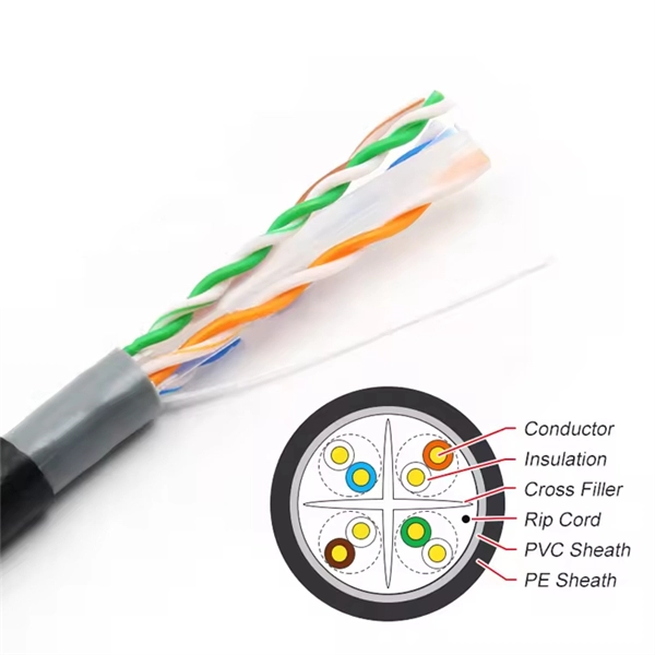
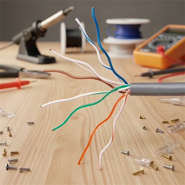
You might have bad connections or lose signal if you bend them too much. Rough handling can also cause problems. Clean them often and manage them with care to stop these issues. If you act early, you will have less downtime. Your network will work better and stay smooth. Proper installation and regular maintenance of fiber optic patch cords play a crucial role in achieving optimized network performance, preventing signal errors, and extending service life. This guide addresses expert-certified best practices applied by professionals in the telecommunications, data. Patching operations must follow principles of neatness, aesthetic cabling, ease of operation, and minimal space usage within ODF frames, optical cross-connects, and integrated boxes. Patch cable lengths should be controlled with a surplus of no more than 500mm. Never use patch cables that are too. Effective fibre optic cable management is crucial for ensuring network reliability, performance, and long-term efficiency. Poorly routed cables, inadequate strain relief, and excessive bending can result in signal loss, increased maintenance, and costly downtime. Incorrect cable lengths can lead to signal attenuation, which refers to the loss of signal strength as it travels through the cable. Plan your fiber patch cord.
[PDF]