The Feeder: Carries power from the main panel to a sub-panel. It feeds the distribution board. No lights, motors, or outlets are directly connected to it. The Branch Circuit: Carries power from the sub-panel directly to the final load (like an induction motor, a lighting fixture . A feeder in electrical distribution is a circuit that carries power from a substation to the area where customers need it. Think of it as the main highway in an electrical network: it moves large amounts of electricity at medium voltage (typically 5 to 35 kV) from a distribution substation outward. Electrical distribution is the final stage in the delivery of electricity to end users. Most share many common characteristics. Figure 1 shows a typical distribution circuit, and Table 1 shows typical parameters of a distribution circuit. The main. multiwire). Branch device and terminates at another circuits are usually low current (30 amps or distribution center, panelboard, or load less), but can also supply high curre ts. A basic branch circuit is made u o the load. Some branch circuits main distribution center and extend to. Feeder lines represent a fundamental part of this hierarchy, acting as the necessary bridge to carry significant amounts of electrical current beyond the main service equipment to secondary distribution points. A feeder can connect two substation buses in parallel to ensure stable power and continuous service for the loads from each bus. If one source has a power.
[PDF]

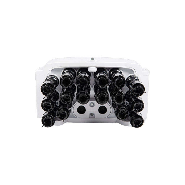
This article provides a detailed technical comparison between fiber optic and copper cables, offering a clear perspective for engineers, network architects, and procurement managers. The core distinction between the two technologies lies in the physics of data. There are significant differences in performance between ADSS cables (all-dielectric self-supporting optical cables) and traditional optical cables, which are mainly reflected in the following aspects: 1. This type of fiber optic cable is designed to support its own weight without the need for additional support structures like messenger wires. The ADSS. There are several factors to assess when deciding which cable type is right for your application, including speed of connection for new customers, ease of changes and repairs, installer certification requirements, and the ability to expand the network over time. ADSS Fiber Optic Cables are a type of optical fiber cable designed specifically for. All-dielectric self-supporting (ADSS) cable is a type of optical fiber cable that is strong enough to support itself between structures without using conductive metal elements. It is used by electrical utility companies as a communications medium, installed along existing overhead transmission.
[PDF]
It can occur due to overloaded circuits, short circuits, or ground faults. Solution: Identify the Cause: Check if the breaker is tripping due to overloading. This often happens when too many devices are plugged into one circuit. Reducing the load on the circuit or redistributing. It's shutting off power because something on that circuit isn't safe. The tripping is a warning signal, not a malfunction. But what's causing it? And more importantly, does it need an expensive fix, or is this something simple? The good news: Most circuit breaker trips have straightforward. The main circuit breaker is designed to protect the electrical system in a building or home from overload and potential fire hazards. There are several reasons why a main circuit. A breaker box acts as the central hub that receives electricity from the utility company and distributes it to various circuits in your home. Homeowners will want to hire an electrician to determine the cause of the frequently tripping circuit breaker. When they start tripping, overheating, or making strange noises, it's more than just an inconvenience - it's your home's cry for help. In this guide, we'll walk through these. If you notice that your circuit breakers are often tripping, don't worry. It's a typical issue. Below, you'll find reasons why this occurs and tips to avoid it moving forward. Get a handle on your circuit breaker problems! Circuit breakers are protection devices for electrical circuits.
[PDF]

In the following tutorial, we will show how to wire 120V single-phase and 240V split-phase circuit breakers and loads inside a residential main panel. The figure below shows a typical breaker panel used for 120V and 240V circuits. Messy distribution boxes are dangerous and very hard to fix. You will learn to build a safe, efficient, and professional electrical system today. Circuit breaker wiring configurations involve organizing main switches, busbars. A breaker box, also known as a circuit breaker panel, is an essential component of any electrical system. It is responsible for distributing electricity throughout a building, ensuring that each circuit receives the proper amount of power. To understand how a breaker box works, it is helpful to. Each circuit is protected by a circuit breaker, a safety device that automatically shuts off power if it detects an overload or a fault. If you're looking to replace an old fuse box replacement or upgrade your home's power capacity, you'll be dealing with the load center or service panel. The distinction between 1P and 2P circuit breakers plays a pivotal role in determining the appropriate protection level for various circuits. When installing or troubleshooting a power distribution system, understanding how to correctly connect the main electrical supply to the control panel is crucial.
[PDF]
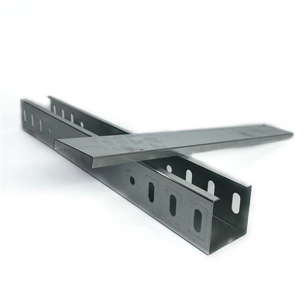
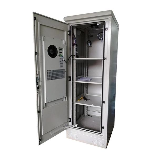
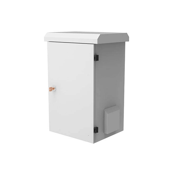
This guide breaks down everything you need to know about electrical distribution boxes in plain English. We'll explain what they are, the different panel types you'll encounter, NEC 408 requirements that govern their installation, and common applications for each type. The power distribution boxes deliver electricity from the main electrical main to other circuits. Several distribution boxes are designed for specific use in offices or industries. Main Distribution Board (MDB) 2. Each. Distribution boxes, also known as electrical distribution boards or panels, are pivotal components in electrical systems, ensuring the safe and organized distribution of electrical power throughout residential, commercial, and industrial environments. It receives power from the main electrical supply and divides it into separate circuits, each. Electrical control panels and distribution boxes are the backbone of modern electrical systems. From powering homes and industrial facilities to supporting medium-voltage infrastructure, these enclosures ensure safe, efficient, and reliable power distribution. Whether it's a small electrical.
[PDF]
Chad power strips and PDU power distribution units for surface mount, rack mount and general purpose applications. Multiple outlet power strips are manufactured in accordance to Chad standards with agency approvals. Quality Chad power strips, in stock, for standard duty applications up to. Lex Products offers a full range of portable power distribution boxes and units, specifically engineered for indoor and outdoor use for the entertainment, industrial and military industries. Our power distribution boxes range from 20-800 Amps and are well known for being durable, long lasting and. United Rentals is a leading provider of power distribution equipment for rent, featuring cables, transfer switches and power distribution boxes. Whether you're planning an event or managing backup power in case of outages, our team of experts can find the right power distribution rental equipment. PREMIUM CONSTRUCTION POWER DISTRIBUTION BOX: Crafted by WESTERN, the 6506TLSX Temp power box features a durable blend material for long-lasting performance in demanding environments. Our custom-based products are able to match up your distinct needs.
[PDF]
In a theatre, a specialty panel known as a dimmer rack is used to feed stage lighting instruments. A U.S. style dimmer rack has a 208Y/120 volt 3-phase feed. Instead of just circuit breakers, the rack has a solid state electronic dimmer with its own circuit breaker for each stage circuit. This is known as a dimmer-per-circuit arrangement. The dimmers are equally divided across the three incomin. OverviewA distribution board (also known as panelboard, circuit breaker panel, breaker panel, electric panel, fuse box or DB box) is a component of an that divides an electrical power feed into subsidiary. North American distribution boards are generally housed in enclosures, with the positioned in two columns operable from the front. Some panelboards are provided with a door covering th. This picture shows the interior of a typical distribution panel in the United Kingdom. The three incoming phase wires connect to the busbars via a main switch in the centre of the panel. On each side of the panel are two.
[PDF]
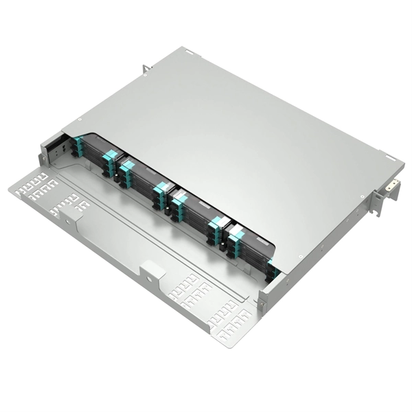
Fiber optic connectors are the backbone of high-speed data transmission, but choosing the right interface—SC, LC, or MPO—can make or break your network's efficiency. In this head-to-head comparison, we analyze their size, port density, performance metrics, and ideal use cases, backed by data charts. They use precision ferrules and alignment sleeves to connect two fiber cores, maintaining light transmission efficiency. Because of this, it's no surprise that fiber optic connectors are in high demand across several industries. Their primary function is to precisely align the end faces of two optical fibers via an intricate mechanical structure to minimize optical signal transmission loss. The basic structure includes components such as. Fiber optic connectors are essential components in optical communication systems, enabling quick and stable connections between fibers. They are. LC, SC, FC, ST, MPO/MTP compared: ferrule sizes, polishing types, insertion loss, and a decision flowchart to choose the right fiber connector for your application. This allows for quickly connecting and disconnecting of fiber optic cables without splicing. The connector features a ferrule, the connector end piece that holds and secures the fiber and aligns it for light.
[PDF]

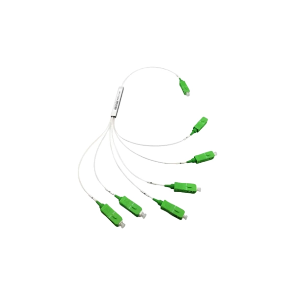
Key finding: This paper develops analytical models and design procedures of ultra-wideband Wilkinson power dividers using linearly tapered transmission lines (TTLs) which provide size reduction and broadband performance. Read more. Power dividers are the passive electronic equipment used for splitting the power. They are now being employed in a variety of communications applications such as telephonic, antennas configurations, mobile connectivity, internet technology, & optics, etc. They come up with very low loss, operate at. RF and microwave power splitters and dividers create two copies of the same signal, while ideally preventing crosstalk between the outputs. Doing this with minimal loss while maintaining signal integrity is a challenge. In this article we explain how power splitters work and what the tradeoffs are. The rise of wireless connectivity requirements for applications such as Internet of Things (IoT), cellular, and automotive electronics is resulting in systems that are increasingly using RF signals, components, and subsystems. Often, designers need to direct these signals to more than a single. A power divider is a passive electronic device used in radio frequency (RF) and microwave applications to split an input signal into multiple output signals with equal or specified power levels, while maintaining impedance matching to minimize signal reflection and loss. How can power dividers.
[PDF]
Here we design a LASER diode driver circuit with adjustable voltage regulator LM317 to drive red color 650nm 50mW laser diode. The function of the Laser diode driver is to provide a constant current to t.
[PDF]
In, a transimpedance amplifier (TIA) is a to converter, almost exclusively implemented with one or more (opamps). The TIA can be used to amplify the current output of, photo multiplier tubes,, and other (that are modeled well as a ) into a usable voltage.
[PDF]

In this tutorial video, we will show you step-by-step how to safely and effectively remove an optocoupler from a circuit board using desoldering wick. We will walk you through the tools you will need, the proper technique for using the desoldering wick, and the precautions to take to av. more In. Whether you're replacing a faulty component, salvaging parts from an old board, or correcting a soldering mistake, knowing how to desolder effectively is essential. This guide will walk you through the tools, techniques, and best practices for desoldering components from a circuit board safely and. Desoldering is a process that removes the solder and components from a printed circuit board or any other type of electronic assembly. This is a meticulous process and it can easily damage the board, or the components, if not properly done. Thus, it is important to know how to desolder properly. If you're desoldering a battery from a circuit board, use flush cutters to cut each wire one-at-a-time to isolate the battery before you desolder the wires. Whenever possible, create an indirect path by soldering connectors onto the battery and the circuit board. This reduces the chance of an. Sorry, an unexpected error has occurred. Why Publish? The Ultimate Guide to Desoldering: From using desoldering irons to sketchily knocking breadboard components off on the side of a table, there are tons of ways to remove components from a circuit board.
[PDF]
The PL-1000D simultaneously monitors up to 16 fiber strands, eight on the OTDR and eight on the OSA, and operates standalone over dark fiber, lighted fiber, or a third party network without impacting network traffic. The device monitors the entire D. The PL-1000D simultaneously monitors up to 16 fiber strands, eight on the OTDR and eight on the OSA, and operates standalone over dark fiber, lighted fiber, or a third party network without impacting network traffic. The device monitors the entire DWDM C-band spectrum and provides the optical spectrum, OSNR, and OTDR measurements of the fiber. The OTDR locates fiber cut by sending high powered optical pulses into the fiber and creating Rayleigh back-reflections. The returning signals are measured and calculated, indicating the accurate location and intensity of the fault. The OTDR supports GIS (Geographic Information System) using Rest API, enabling precise geographic location of disrupt. The OSA enables the user to monitor the OSNR and optical spectrum of each fiber and shows a full, accurate and detailed picture of the wavelengths used in the fiber. OSADiagram Graphical Display of the OSA, from PacketLight's LightWatch NMS Please contact usfor a quote or further assistance.
[PDF]
The panel box contains a series of circuit breakers or fuses that control the distribution of electrical energy to individual circuits throughout the building. An electrical panel box, also known as a breaker box or a distribution board, is a crucial component of any electrical system. It serves as a central hub for distributing electricity throughout a building, ensuring that power is delivered safely and efficiently to all the required locations. In this article, we'll explain what a series circuit is, how to draw a series circuit diagram, calculate. A distribution board or distribution box is where the main power supply is distributed to multiple loads. And all the switching and protective devices are installed in the distribution box. Single Phase Distribution Box generally consists of Double Pole MCBs, Single Pole MCBs, and RCCBs. Distribution. STEP 1: The flow of electricity begins at the g nerating station. at S the ation Switchyard. This is done to minimize the losses. STEP3: The ransmission Substation, increases the step-up voltage transformer from 69,000 to 765,000 volts. The distance it will go and the type of facilities distributed.
[PDF]