
The max insertion loss of a fiber patch cable is 0. 75 dB (the maximum acceptable value) in the TIA standard. Insertion loss (IL) and return loss (RL) are key performance indicators of fiber optic patch cords. This article explains their concepts, standards, testing methods, and FiberMania's quality assurance workflow to ensure optimal network performance. Fiber optic patch cords are crucial components in. A: Fiber optic loss refers to the reduction in signal strength as it travels through the fiber optic cable. This can be due to various factors, including attenuation, connectors, and splices. Q: How is fiber optic loss measured? A: Fiber optic loss is typically measured using an Optical Loss Test. The estimate, called a "loss budget" is calculated using typical component losses for each part of the cable plant - the fiber, splices and/or connectors. If the measured loss exceed the calculated loss by a significant amount (remembering the inherent uncertainty in all measurements), the system. Insertion loss is usually shortened to IL, and the unit of measurement for insertion loss is dBm. ) in transmission systems. It is the power attenuation of the signal after. At TARLUZ, we specialize in manufacturing high-performance fiber optic patch cords that comply with global industry standards, ensuring optimal signal integrity and long-term stability.
[PDF]

The typical specification range of return loss of a fiber connector is -15 dB to -60 dB. Return loss is also known as reflection loss. It indicates the amount of signal reflected back to the transmitting end. Return loss refers to the power loss caused by the reflection of part of the signal back to the signal source during transmission due to the discontinuity of the transmission. Insertion loss, also known as attenuation, is the loss of optical power that occurs when light passes through a fiber optic connector. It is caused by factors such as misalignment, air gaps, and imperfections in the connector components. The lower the insertion loss, the better the performance of. Reflectance (which has also been called "back reflection" or optical return loss) of a connection is the amount of light that is reflected back up the fiber toward the source by light reflections off the interface of the polished end surface of the mated connectors and air. It is also called. Insertion Loss (IL) is the amount of optical power lost as the signal travels from one point to another in a fiber optic link, usually across connectors or splices. Formula for. In optical fiber communication, insertion loss and return loss are two important parameters to evaluate the quality of interfaces between some optical fiber components, such as optical fiber connector, fiber patch cable, pigtail fiber, etc. While it's natural to have.
[PDF]
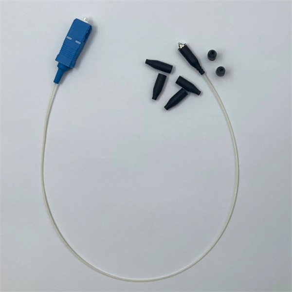
A fiber optic pigtail is a short length of optical fiber —typically 0. 5m to 2m—that has a factory-terminated connector on one end and bare fiber on the other end. The connector end is polished and tested under factory conditions, ensuring low insertion loss and high return loss. In this guide, we will break down what fiber optic pigtails are, how they differ from patch cords, what types exist, and how to select the right one for your project. By the end, you will have a comprehensive understanding of why pigtails deserve a place in every fiber deployment toolkit. Unlike a patch cord—which has connectors on both ends—the bare fiber end of a pigtail is designed to be permanently. The length of a fiber pigtail may seem like a simple detail, but it plays a direct role in how optical signals travel through a network. By understanding how cable length influences light transmission, installers can make better decisions that lead to stable, efficient network performance. This design allows for quick and easy splicing to another fiber or cable, ensuring a secure and efficient connection. Ideal for use in. 🔍 What Is a Fiber Pigtail? A fiber pigtail is a short length of optical fiber that has: In simple terms: A pigtail connects a connectorized interface to a permanently installed fiber via splicing. A standard FTTH.
[PDF]
This guide delves into the structure and working principle of fiber optic connectors and outlines the critical steps for creating a successful connection. Proper connection of fiber optic cables is essential to harness these benefits fully, as even minor errors can lead to significant performance issues like signal loss. This article will guide you through the necessary tools, materials, and methods on how to connect fiber optic cables effectively. This guide will explain the entire set of activities involved in installing Fiber optic cable contractors -from the early planning stage right through testing-for facility managers, IT teams, and low-voltage contractors to build high-performance networks safely and efficiently. The processes. However, working with fiber requires specialized skills and equipment to connect cables properly. This guide will walk you through the complete process of connecting fiber optic cable. Before connecting any fiber cable, you need to assemble the proper preparation tools: With the right tools in. The Fiber Optic Association, Inc. (FOA) was founded in 1995 to help develop the workforce to build the fiber optic networks to support a rapid expansion in communications and the Internet.
[PDF]

Fusion Splicer Settings – Must-Know for Fiber Technicians! 🔧 At D-TECH TRADING, we're demonstrating the essential Fusion Splicer settings that every fi. more. Auto Mode is the most intuitive and user-friendly splice mode. The fusion splicer automatically detects the fiber type, such as single-mode (SM), multimode (MM), or dispersion-shifted (DS) fibers, and adjusts parameters like arc power and heating time accordingly. Applications: Ideal for beginners. Page 1 Fusion Splicer 19R+/70R+ Quick Reference Guide Splice Operation • When splicing only standard SM fibers (ITU-T G. 652), “SM AUTO” mode is recommended. It also outlines instructions for keypad usage. st Instruction manual Fusion Splicer Please read this instruction manual carefully before operating the equipment. Adhere to all safety instructions and warnings contained in this manual. Keep this manual in a safe place. There is a change without a previous notice. We are not responsible for the. Fusion splicing is the bedrock of high-performance fiber optic networks, enabling seamless signal transmission through permanent, low-loss fiber joins. As a leading provider of fiber optic infrastructure, Weunion leverages cutting-edge tools like the AI9 and AI10 fusion splicers, paired with.
[PDF]
Breakaway head bolts are used to apply a precise gripping force to hold the cable without affecting optical fiber performance. “Securing” fiber optic cable goes beyond just preventing it from moving; it encompasses protecting its delicate core from physical stress, environmental degradation, and ensuring long-term signal integrity. Achieving this requires a combination of thoughtful design, appropriate materials, and. Describe the system used for installation and delivery of OPGW fibre optic cables. - SCOPE This document covers all the activities usually performed by PRYSMIAN for on-site installation of OPGW fibre optic cables, including transport, installation, accessory assembly, verification of optical. The FIBERLIGN Cushion Clamp uses a combination of structural reinforcing rods (SRR) and elastomer inserts at the ends of the clamp halves to protect the OPGW from damage at support points. Clamp halves and SRR are high-strength aluminum alloy. Fastening hardware is galvanized steel. SRR cannot be. This manual is formulated in accordance with IEEE 1138 - 2008 and IEEE 524 - 1992, etc. OPGW has dual functions of aerial ground wire and fiber communication. The installation rules of OPGW are basically the same as the. The Fiber Optic Association, Inc. (FOA) was founded in 1995 to help develop the workforce to build the fiber optic networks to support a rapid expansion in communications and the Internet.
[PDF]
This step-by-step guide will walk you through the process of terminating fiber optic cable, from inspecting the cable to polishing the connector. As an experienced technology writer who has covered broadband advancements for over a decade, I aim to provide readers with trustworthy instructions endorsed by industry experts. Having. Unplugging a fiber optic cable from a modem is a task that requires careful handling to avoid damaging the delicate fibers within the cable. Fiber optic cables are different from traditional copper cables, as they use light to transmit data, and the connectors are more sensitive. Here is a. In this video, I'm showing you how to remove an optical fiber cable connector from a modem. This is a popular video tutorial that is often requested by viewers. Did you find drooping wires, downed lines, or AT&T equipment in a yard or on the street? Let us know. Call us anytime at 800. Have AT&T service? Provide your account info and say, Line is down. This protects the internal electronic components and helps ensure the fiber port is inactive, minimizing the risk. This fiber optic cable is going to need to be unplugged and moved. Is this something that requires a Verizon support tech or can I do it? If so is it as simple as disconnecting and reconnecting or would I have to call support to "reinitiate" my setup. Not my pic, but didn't feel like moving the.
[PDF]

Not all splitters are created equal. Here are the main types you'll encounter: The "1×N" notation indicates one input fiber and N output fibers. A 1×2 splitter divides the signal into two outputs, while a 1×8 splitter divides it into eight. The more splits, the. By dividing a single optical signal from a central Optical Line Terminal (OLT) into multiple outputs for Optical Network Terminals (ONTs) at users' homes, splitters eliminate the need for dedicated fibers to each residence—slashing infrastructure costs while scaling network reach. This guide. A fiber-optic splitter, also known as a beam splitter, is based on a quartz substrate of an integrated waveguide optical power distribution device, similar to a coaxial cable transmission system. The optical network system uses an optical signal coupled to the branch distribution. The fiber optic. Optical couplers can split or join signals in fibers. You can connect many users to one port with 1:n or 2:n splitters. These devices work both ways, which helps strong network communication. In a Passive Optical Network (PON), a single optical fiber carries massive amounts of data using light. They are named by the number of inputs and outputs, so a splitter with one input and 2 outputs is a 1X2, and a PON splitter with one input and 32 outputs is a 1X32.
[PDF]
Calculate cable tray fill ratio, weight loading, and derating factors for multi-standard compliance. This calculator features an interactive interface with advanced visualizations. Open the full calculator for the best experience. IEC 61537 covers cable tray and cable ladder systems for the support and accommodation of cables, while NEC Article 392 governs cable. Article Summary: A compliant cable tray installation requires a thorough understanding of NEC Article 392, proper structural support, and precise installation techniques. This guide covers the critical steps, from selecting the right electrical cable tray and performing accurate cable fill. Properly sizing your cable tray is critical for safety and compliance. Follow these simple steps: Define Tray Dimensions: Enter the width and depth of your planned cable tray (in mm or inches). Save your cable tray sizing calculator results as branded PDF. A 12 in ladder tray loaded to 4 in depth has 48 sq in of tray area; with 24 #12 THHN conductors at 0. 0133 sq in each, the screen is about 0. This page is a preliminary cable-tray occupancy screen for early layout work. It adds cable planning area, compares. This publication is intended as a practical guide for the proper and safe* installation of cable ladder systems, cable tray systems, channel support systems and associated supports. Cable ladder systems and cable tray systems shall be manufactured in accordance with BS EN 61537, channel support.
[PDF]

If you are ever in need of checking your ONT, this video will show you how to do so and what it is you are looking for. Always remember to securely close the box afterwards to prevent any damage to the facilities inside. more. A fiber termination box is the standard instrument used in fiber optic networks to connect, secure, and protect optical fibers at the terminating point. It functions as a junction between the incoming fiber cable and the outgoing customer-side fiber cable, where one fiber can be spliced, patched. Open the Fiber optic terminal box. Check and prepare installation tools and accessories. Prepare the cable according to the design. An ONT, or Optical Network Terminal, is the box where your fiber internet connection enters your home to power your fiber network. Your ONT is typically located in your garage, basement or outside your home within a few feet of your home's power box. It serves as a termination point for optical fibers, providing a secure and organized space for connecting and managing fiber optic cables. A fiber pigtail is a specific hardware connection used for cable termination. Proper installation and maintenance of FTBs are essential to ensure the reliability and performance of the network infrastructure.
[PDF]

Learn how to splice fiber optic cable using fusion splicing with this complete step-by-step guide. Includes tools, best practices, loss standards (ITU-T G. 652), cost analysis, and FAQs for network engineers and installers. 5,398 fiber splicing stock photos, vectors, and illustrations are available royalty-free for download. Template technician Fiberoptic Fusion Splicing. Worker connecting for Cable Internet signal and Wire connection with Fiber Optic Fusion Splicing machine,fiber optic cable splice machine in work. Splicing fiber optic cable is an extremely important phase for making dependable, high-speed communication infrastructures. Regardless of the type of fiber network you're deploying, be it for telecom, enterprise data centers, or smart city infrastructure, fusion splicing provides the benefits of. In this guide, we cover the basics of fiber optic splicing, how to perform splicing using two different methods, and finally some best practices to perform good fiber splicing. Ensure Your Splicing Tools are Clean – #2. For network managers and technicians, a poor splice can lead to significant signal degradation, network downtime, and costly troubleshooting. At Turn-Key. 🔧 Watch a real-time fiber optic splicing demo in action! In this step-by-step tutorial, learn how to splice fiber optic cables like a pro — perfect for telecom technicians, network engineers, and field techs.
[PDF]

To set up your router for fiber internet quickly, connect the router to your fiber modem, access the router's settings via a web browser, and input the provided ISP credentials. Make sure to update the firmware, configure Wi-Fi security, and customize your network name for. Q: How do I install my broadband modem and set up my Internet connection? Installing your broadband modem and setting up your Internet connection involves several steps. First, you need to physically connect your modem to your computer using an Ethernet cable or wirelessly through a router. Next. This wikiHow guide will walk you through setting up a Wi-Fi connection in Windows XP and connecting to the internet. We'll also cover the risks so you know what you're getting into. Check for or install a wireless adapter. Enable Wireless Zero Configuration. Right-click the network icon. Why Use Fiber Optic Internet? Before diving into the setup, let's quickly. Setting up a home network on Windows XP can seem like a daunting task for beginners, but with the right guidance, it becomes a straightforward and rewarding endeavor. This beginner's guide is designed to walk you through the easy steps necessary to establish a functional network within your own. This article provides a detailed guide for establishing internet connectivity in Windows XP via dial-up modem, Ethernet, and Wireless connections, including troubleshooting common issues.
[PDF]
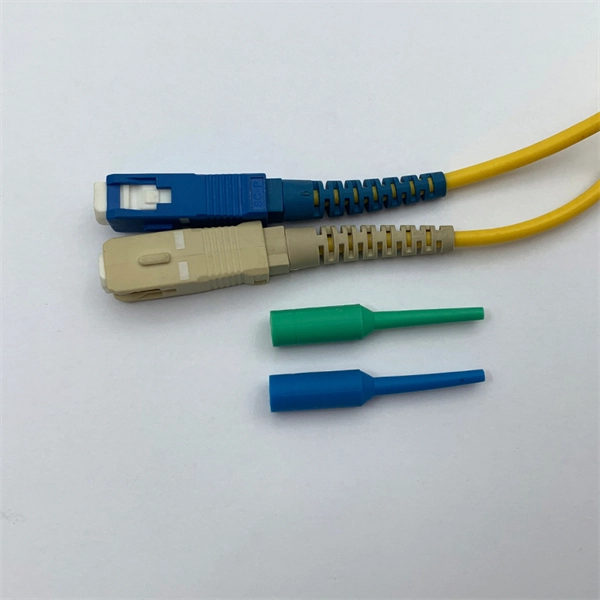
Fiber optic connectors, also known as terminations, connect two ends of fiber optic cables. A fiber optic connector is a mechanical device used to align and join optical fibers, enabling light to pass through with minimal loss. Unlike fiber splicing, which is permanent, connectors allow for easy connection and disconnection of cables, making them ideal for maintenance and flexibility in. This article provides a complete, practical guide to choosing the right fiber optic connector for modern networks. It explains all major connector types (LC, SC, MPO/MTP, ST, FC, rugged industrial connectors), the differences between simplex/duplex, single-mode/multimode, boot types, polish types. Where copper twisted pairs tend to terminate with an RJ45 plug, fiber optic connectors come in all sorts of shapes and sizes, with all manner of different use cases in mind. However, with several connector types available, each with unique designs and uses, it's important to understand which one fits your application best. In this. Picking the most appropriate fiber cable connector type from the numerous optical connector types available has a direct bearing on network performance, scaling up, and ongoing maintenance. The connector features a ferrule, the connector end piece that holds and secures the fiber and aligns it for light.
[PDF]

This guide breaks down their technical differences, performance metrics, real-world applications, and how to choose the right one for your network—all optimized for Google SEO and packed with actionable insights. Introduction: Why Fiber Optic Cable Type Matters. Single mode fiber optic cable is made up of a small diameter glass or plastic core surrounded by cladding, which is a layer of reflective material. This small diameter core, typically around 9 microns in diameter, allows only one mode of light to pass through, resulting in a narrower beam of light. But not all fiber cables are created equal: multimode (MM) and single mode (SM) fibers are the two primary types, each engineered for specific use cases, from short-range data center connections to transcontinental telecom backbones. Whether you are an IT specialist, a network manager, or just a curious individual interested in the. As explained by the Fiber Optics Association, fiber optics is the communications medium that sends optical signals down hair-thin strands of extremely pure glass cores. The core is surrounded by the cladding that traps the light in the core. Fiber types are identified by the diameters of the core. The article compares single-mode and multimode fiber optic cables, especially in how their core design, light propagation, and use-cases differ. Core Diameter Single mode fiber: one that has a small light-carrying core that is about 9 micrometers (µm) in diameter.
[PDF]
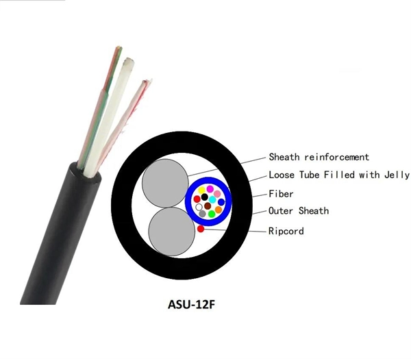
Fiber optic cables are essential components in modern data transmission infrastructure. They support high-speed, interference-resistant communication and are particularly effective in applications that require high bandwidth, low latency, and strong signal integrity. Unlike traditional copper or. Fiber-optic communication is a form of optical communication for transmitting information from one place to another by sending pulses of infrared or visible light through an optical fiber. The light is a form of carrier wave that is modulated to carry information. While the glass fibers inside are fragile, modern fiber cables are engineered to withstand crushing forces, extreme temperatures, and even rodent attacks—making them vital for. In the high-speed world of fiber optic communication, data travels at the speed of light. But what happens when that light fades? Optical Signal Attenuation is the single greatest factor limiting the distance and performance of your network. Fiber optic cables transmit data in the form of light pulses, a process that occurs at a fraction of the speed of light. This translates to data transfer speeds of up to several terabits per. This combination of this plus optical fiber (a high-performance transmission medium made of glass as thin as a human hair capable of trapping optical signals and transmitting them over long distances without significant attenuation) were game changers and set the stage for optical-based.
[PDF]