In short length cables a visual fault locator (VFL) can find where the cut is or find the bad connector at patch panels. For longer distance cables, the use of an OTDR is required. Once the fault is located, fusion splicers and splice-on connectors can be used to complete the repair. Fiber optic cables are the backbone of modern networks, delivering fast and reliable data transmission. Accidental cuts, breaks, or other damage can disrupt your network and cause costly downtime. With the right tools and techniques, you can efficiently repair damaged fiber cables and restore. Fiber optics offers advantages like EMI immunity and low attenuation (0. 2 dB/km), but it's fragile—susceptible to breaks, bends, and contamination. Repairs focus on restoring the light path with minimal signal loss (<0. A fusion. Visual inspection and specialized tools like OTDRs, OPMs, and VFLs are essential for identifying and locating physical damage or faults in fiber optic cables. Emergency restoration planning involves implementing backup power solutions, network redundancy planning, and strategies for prompt. Fiber optic cables are critical components of modern communication networks, transmitting vast amounts of data at lightning speeds.
[PDF]

While optical power meters are the primary power measurement instrument, optical loss test sets (OLTSs) and optical time domain reflectometers (OTDRs) also measure power in testing loss. TIA standard test FOTP-95 covers the measurement of optical power. This measurement is the basis for loss measurements as well as the power from a source or presented at a receiver. Typically both transmitters and receivers have receptacles for fiber optic connectors, so measuring the. You need a power meter to measure power in a fiber optic system; most power meters come with a screw-on-adapter that matches the connector being tested and a little aid from the network electronics to turn on the transmitter. During the measurement of power, the meter must be set to the proper. Fluke Networks sets the standard in network testing with its advanced range of fiber optic power meters and fault locators, designed to ensure the highest precision in fiber optic meter readings and power evaluations. This is measured in decibels (dB). Splitters, fusion splices, connectors and. To use a power meter for fiber optic testing, always clean connectors first with lint-free wipes or click-to-clean tools. Select the correct wavelength and set your reference. Consistent procedures ensure accuracy.
[PDF]

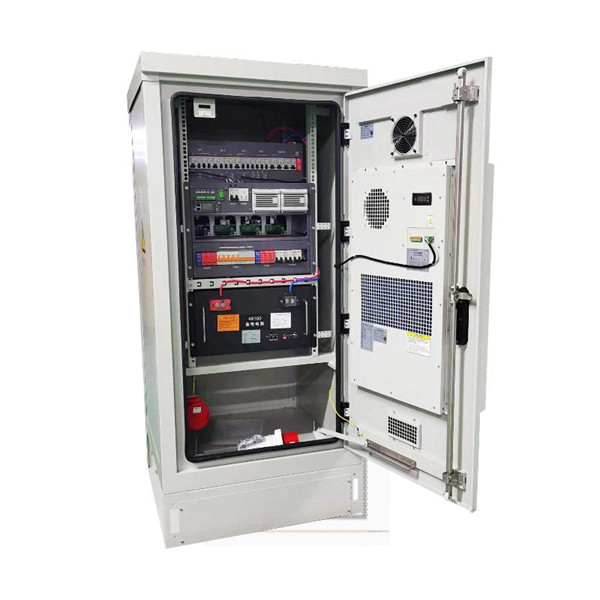
Optical fibers or fiber cables can be used for transmitting optical power from a source to some application. In their served areas will be power generating stations, alternative energy sources (solar, wind, geotherman, etc. ), substations for distribution and microgrids. These networks must be monitored and managed to ensure reliable power for the utility's customers. For monitoring and managing networks. Low voltage cables are mounted on poles in the "telecom space," well below power cables. Optical power ground wire (OPGW) is an electrical power ground with fiber optics in the center of the conductor. That conversion can be done with a photovoltaic cell. The Commission, on June 22, 1965, noting that the increasing demand for underground electric and communication facilities in California has brought about substantial increases in the construction of such facilities, and that it appeared it may be desirable, pursuant to Sections 761, 768 and 8056 of. One choice is optical power ground wire (OPGW). This conductive cable is run at the top of the tower or pole to be the ground conductor and protect the power cables from lightning. The fiber. While fiber optics is essential for internet service providers to deliver higher bandwidth and faster transmit speeds, there are also many crucial benefits of fiber optics in energy and power. Utility companies face various challenges as they work to deliver reliable energy to homes and industries.
[PDF]

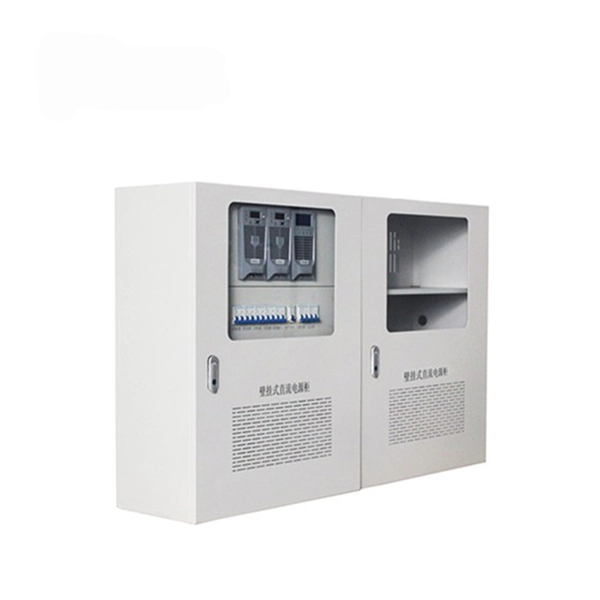
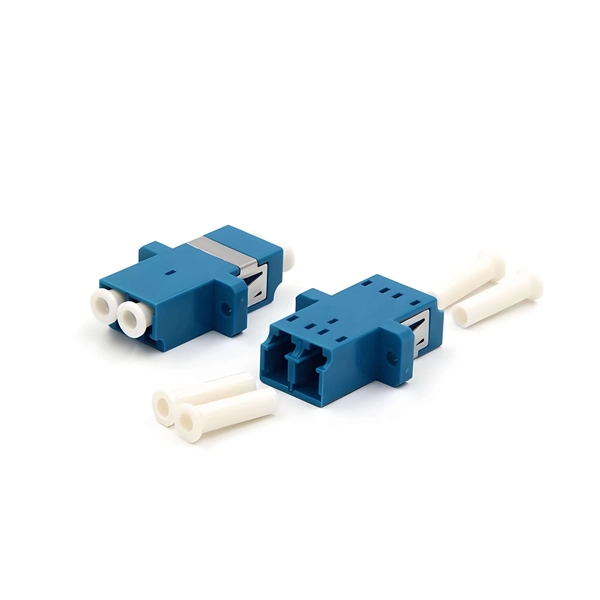
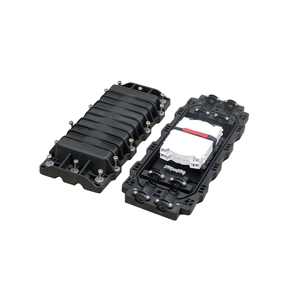
The compact 1 port ftth fiber termination box can hold 2 cores splicing, termination and coil up to 30 meters long for cable management in FTTH network. The 1 port fiber termination box is available for fiber optic cable coiling, it is great to connect optical cable and pigtail and protect fiber splices from damage. It is small, lightweight, and offers the function of fiber splicing, storage, and termination, mainly used in residential buildings. The maximum distance for single mode fiber optic cable can extend up to several hundred kilometers, making it ideal for long distance data transmission. One type of single mode fiber is known as “G. 652,” which is commonly used in telecommunications networks. Here are some general guidelines: 1. The shorter distance accounts for the. A fiber optic distribution box (FDB) is a protective enclosure for managing fiber optic cables. It organizes connections, splices fibers, and distributes signals in networks like FTTH (Fiber-to-the-Home) or FTTB (Fiber-to-the-Building). It acts as a central point for terminating, splicing, and distributing these cables, providing necessary protection and. The Fiber Optic Association, Inc. (FOA) was founded in 1995 to help develop the workforce to build the fiber optic networks to support a rapid expansion in communications and the Internet. The charter of the FOA was to promote professionalism in fiber optics through education, certification, and.
[PDF]
Power consumption of fiber optic cables can range from 0. 01-100 W/Gbps depending on the length of the cable (chart below). To ensure that fiber-optic connections have sufficient power for correct operation, calculate the link's power budget when planning fiber-optic cable layout and distances. The power budget is. Attenuation is the difference between the launch power of the signal from the transmitter and the power of the signal at the receiver. Each. The power consumption of coherent fiber-optical communication systems is beco-ming increasingly important, for both environmental and economical reasons. The data traffic on the Internet is increasing at a faster pace than that at which optical network equipment is becoming more energy efficient. With the growing global deployment of Fiber-to-the-Home (FTTH) networks driven by the demand for ensuring high-capacity broadband services, mobile network operators (MNOs) face challenges of excessive energy consumption (EC) of wired optical access networks (OANs). You use power budget calculations to verify whether an optical link—FTTH, ODN, backbone, or data center—can operate reliably under all. Reduced power consumption: 800G optical devices can achieve energy savings at the optical and system level, such as using more efficient modulation formats, optimizing circuit design, and reducing power density.
[PDF]
Recommendation ITU-T L. 12 specifies splices of single-mode and multimode optical fibres. It describes suitable procedures for splicing that should be carefully followed in order to obtain reliable splices between single optical fibres or ribbons. Typical applications of these methods include aerial, buried, and underground splices. (2) American National Standard Institute/National Fire Protection Association (ANSI/NFPA) 70, 1993. § 1755. 370 - RUS specification for seven wire galvanized steel strand. 400 - RUS standard for. ation or liability to users of this publication. Existence of a standard shall not preclude any member or nonmember of NECA or FOA from specifying or using alternate construc Code (NEC) in effect at the time of publication. Because they are quality standards, NEIS® may in some instanc s go beyond. RUS standard for splicing copper and fiber optic cables. (FOA) was founded in 1995 to help develop the workforce to build the fiber optic networks to support a rapid expansion in communications and the Internet. The charter of the FOA was to promote professionalism in fiber optics through education, certification, and.
[PDF]

The FLS-140 is the easiest way to identify optical fibers from end to end and locate polished connector endfaces. Its red laser shines through most yellow-jacketed optical fibers to help you pinpoint breaks, bends, faulty connectors, splices and other causes of signal loss. A Visible Fault Identifier (VFI), also referred to as a Visual Fault Locator (VFL), is an essential tool for fiber installation and maintenance technicians. AFL's compact VFI4 injects high-powered red-laser light to provide exceptional brightness and range for locating defects in single-mode and. The B5 Rechargeable Red Light Pen is a professional 650nm visual fault locator designed for fiber optic network maintenance, installation, and troubleshooting. Its advanced rotary automatic lift laser head ensures smooth operation, while the integrated LED lighting improves visibility in low-light. Whether installing or troubleshooting, the Visual Fault Locator (VFL) is an essential tool that quickly and easily locates problem areas in fiber cables. By pinpointing the exact location of fiber damage, technicians can diagnose, troubleshoot, and fix the problem efficiently. The VFL is also used. The state, throughput, and identification of an optical fiber can be easily checked with fiber testers by coupling highly visible laser light into the optical fiber. A high intensity visible red laser beam is precision-coupled.
[PDF]

Its red laser shines through most yellow-jacketed optical fibers to help you pinpoint breaks, bends, faulty connectors, splices and other causes of signal loss. It has a reach of up to 5 km. The RPEN-210 is a necessity tool that should not be missing from any fiber plant manager or fiber optic installing technician. The Visual Fault Locator (VFL) Pen has a visible red light source centered on 650nm. Tool sends visible light over a fiber strand with a 10mW power, good enough to reach. The FLS-140 is the easiest way to identify optical fibers from end to end and locate polished connector endfaces. 5 dBm, but it couples approximately 3 dB less into a fiber. This is a Class 1 unit; the Class 1 limit is +3 dBm. The Class 1 limit (+3 dBm/2 mW) is intrinsically safe in all circumstances and is. This VFL has a fiber stub; its total emission is -1. 30 years of experience in R&D and manufacturing - Jilong JILONG launched the VFL-22M mini red light pen, pocket design, small and portable, integrated VFL/LED function, strong and stable light source, strong penetrating. A visible laser radiation source is one of the simplest devices and is designed to produce red light with a wavelength of 650 nm, which is transmitted through an optical fiber. The main purpose of this device is to locally detect various types of damage (such as breaks, bends, poor splicing, etc.
[PDF]

Communication networks are an integral part of interconnected transmission lines in a power grid, analogous to the spinal cord for control signal and information exchange among substations, data hubs, and load dispatch centers. This article cov. Communication networks are an integral part of interconnected transmission lines in a power grid, analogous to the spinal cord for control signal and information exchange among substations, data hubs, and load dispatch centers. This article covers the major trend and design aspects of fiber optics communication link in power transmission line netwo. The communication network in the power grid is one of the most interrelated systems that require perfect compliance in equipment and protocol selection. While the high voltage components are relatively unchanged over decades in terms of operating principles, the communication protocols and equipment are seeing astonishing advancements every year. S. 2.1 Knowhow of prevailing setupWhile the primary objective is always to get the best solution for the lowest price, in the case of extension projects, the design engineers must also keep an eye on the existing setup. The issue of back-compatibility and upgradationsshould be properly accessed in existing equipment, even more so in the case of proprietary legacy setups. Figure below illustrates one such group of communication equipment in existing substations that might need proper interfacing and compatibility adapters befo.
[PDF]
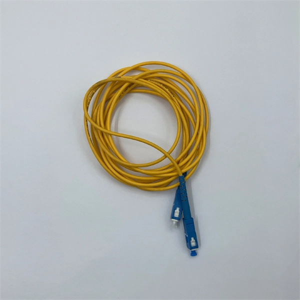
A 4 Core Optical Cable is a fiber optic cable that contains four individual optical fibers within a single protective outer jacket. Each fiber is capable of independent data transmission. A TOSLINK optical fiber cable with a clear jacket. These cables are used mainly for digital audio connections between devices. A fiber-optic cable, also known as an optical-fiber cable, is an assembly similar to an electrical cable but containing one or more optical fibers that are used to carry. This guide covers everything you need to know about 4 core fiber, including its internal structure, TIA standard color coding, and how to choose the right type. They are ideal for long-distance communication and. But generally, the cable core, strength member and outer sheath together make a fiber optic cable. It transmits electricity or information from one place to another. These fibers are used to transmit data as light signals, offering high-speed data transfer capabilities over long distances with minimal loss. Fiber optic cables are crucial.
[PDF]
Fiber optic cable installation costs average $4,500 for most homeowners, with most installations ranging from $1,500 to $7,000. Computer repair costs depend on your project and location. Check with a local pro for your specific job. The installation type you choose and the layout of your. Homeowners and businesses typically pay for fiber optic cable installation based on distance, conduit needs, and labor. The main cost drivers include material type, run length, trenching or aerial work, and any required permits or inspections. This guide provides clear cost estimates, price ranges. Fiber optic cables consist of multiple fibers, each designed for high-speed data transmission. These fibers are thin strands, often as small as a human hair, that transmit data as pulses of light. Data aggregated from Q1 2026 contractor invoices across Texas, Ohio, and North Carolina.
[PDF]

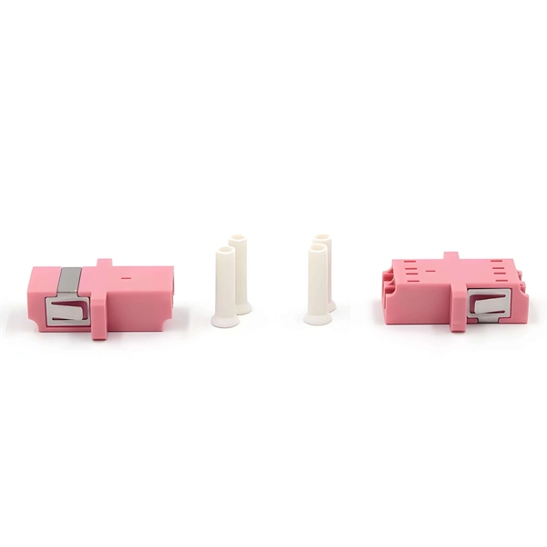
Fiber splitters serve as essential components in optical networks. These devices divide an optical signal from a single input into multiple outputs. This process enables efficient signal distribution across various network points. Fiber splitters function without the need for external. In the intricate web of modern fiber optic networks, where data travels at the speed of light across continents, fiber optic splitters play a silent yet pivotal role. These unassuming devices enable a single optical signal to be divided into multiple paths, making them indispensable for sharing. A fiber splitter, also known as a beam splitter, is a passive optical device that splits an optical signal into multiple signals. By dividing a single optical signal into multiple signals, fiber. Fiber optic splitters are vital in modern communication networks. Fiber optic splitters, such as plcsplitter and fbt splitters, are crucial in maintaining signal integrity, with considerations for IL (Insertion Loss) and RL (Return Loss). They are integral components in the world of telecommunication and data networking, crucial to maintaining reliable and efficient communication infrastructures. There are two primary.
[PDF]
Picking up the best router for fiber internet isn't just about going to the market and choosing one of the best wireless routers. Instead, you need to carefully look at its specs, performance, and the type of security features it offers. Here ar. Picking up the best router for fiber internet isn't just about going to the market and choosing one of the best wireless routers. Instead, you need to carefully look at its specs, performance, and the type of security features it offers. Here are a few things to consider before making a purchase. To find the best routerfor fiber internet, we used our expertise to select items based on key specs, such as speeds, coverage, wireless standards, security, weight, and additional features. We've also delved into and weighted market sentiment and user views to ensure our selections align with users' experiences with these products. However, we don'. Fiber internet can deliver lightning-fast speeds, and a capable router is needed to take full advantage of that. That said, we recommend giving the NETGEAR Nighthawk RS700S a shot, as it supports the Wi-Fi 7 standard and has plenty of gigabit Ethernet ports. On top of that, in our RS700S review, it had excellent range and performance, which gave it.
[PDF]
Market Size by Fiber Type, by Deployment, by Cable Type, by End Use Industry – Global Forecast. The global fiber optic cable market was valued at USD 13 billion in 2024 and is estimated to grow at a CAGR of 10. The Fiber Optic Cable Market Report is Segmented by Cable Type (Armored Cable, Non-Armored Cable, and More), Fiber Mode (Single-Mode Fiber, Multi-Mode Fiber, and More), Installation Type (Aerial/Overhead, Underground/Buried, and More), End-User Industry (Telecommunication, Power Utilities and Smart. The global Fiber Optic Cable Market is anticipated to be worth USD 5. It is expected to grow steadily and reach USD 11. This growth represents a CAGR of 7. 21% during the forecast period from 2026 to 2035. I need the full data tables, segment breakdown, and. The fiber optics industry is projected to reach USD 6. 8 billion by 2029 from USD 3. Rapid expansion of data centers, cloud services, and 5G infrastructure is driving strong adoption of fiber optic solutions. 64% between 2023 and 2028. The market is experiencing significant growth, driven by the increasing demand for high-speed internet connectivity and the expansion of data centers.
[PDF]
They can weigh between 60 to 200 kg per kilometer (39. 7 to 132 pounds per 1000 feet), depending on the design and materials used. The weight of fiber optic cables can vary widely based on the factors mentioned above. However, some general guidelines can provide a rough estimate: Indoor Fiber Optic Cables: These are typically lighter as they require less protection. Indoor cables can weigh anywhere from 10 to 30 kg per. Fiber per Tube *: No of tube(13-24) shall be with black tracer but black* tube(20) with white tracer. Fiber per Tube *: Tube identification with one black stripe. In case of Black tube with white marking. This cable is perfect for headend termination to a fiber backbone, termination of fiber rack systems, multi-floor deployment where select fibers are used at each floor, or intra-building backbones. It is suitable for all indoor applications where fiber optic cabling is needed. Lighter materials reduce overall cable weight 3. Strength and. CommScope all dry outside plant stranded loose tube cables deliver the same proven quality and performance offered in all CommScope cabling solutions. The construction features the use of dry. The Cisco ® family of QSFP-DD modules provide the industry's highest bandwidth density while leveraging the backward compatibility to lower-speed QSFP pluggable modules and cables. The Cisco 400GBASE Quad Small Form-Factor Pluggable Double Density (QSFP-DD) portfolio offers customers a wide variety.
[PDF]