
Fiber optic patch cabling is part of a fiber optic network construction, so the important choice is whether to use multimode patch cords or single mode patch cords. These patch cords aim to achieve the same goal of transmitting optical signals by the means of the construction, performance, and. Fiber optic patch cords, also known as fiber optic patch cables or fiber jumpers, are indispensable components in modern optical networks. They act as the critical link for interconnecting devices like optical switches, servers, and distribution frames. Understanding the various technical. This guide explains what fiber patch cables are, their types, connector standards, where they are used, and how to choose the right one for your data center. It is designed for flexible. But believe it or not, it's very possible that single mode fiber cables are the best option for you. While it is true that multi mode fiber optic cords are better at handling a heavier load than single mode cables, especially where a complex data network is involved, there are some situations where. When it comes to fiber optic patch cords, two primary types are single-mode and multi-mode. Single-mode fibers are designed to carry a single mode of light, allowing for higher bandwidth and longer transmission distances compared to multi-mode fibers. Singlemode fiber optic patch cables support high-speed networks up to 50 times farther than.
[PDF]
In this comprehensive guide, we'll walk through the best practices for installing various types of fiber optic cable, from patch cords to distribution fiber, and provide practical tips to ensure a successful installation. Correct patch-cord installation is essential for maintaining low insertion loss, stable return loss, and long-term reliability in both indoor and outdoor fiber networks. Proper handling, routing, cleaning, bend-radius management, and connector alignment ensure that the optical link meets design. Proper installation and regular maintenance of fiber optic patch cords play a crucial role in achieving optimized network performance, preventing signal errors, and extending service life. This guide addresses expert-certified best practices applied by professionals in the telecommunications, data. Proper connection of fiber optic cables is essential to harness these benefits fully, as even minor errors can lead to significant performance issues like signal loss. Whether you're connecting a data center, a corporate network, or a high-density fiber infrastructure, correct installation methods are essential. Yingda. In today's high-performance networks, fiber optic patch cables are the lifelines that ensure smooth data flow across switches, servers, and routers. Even the most advanced optical transceivers can only perform at their peak when paired with properly installed, clean, and precisely managed fiber.
[PDF]
Fiber optic patch cords do not have “polarity” in the sense of electrical positive and negative terminals, like a battery. Plugging them in “backwards” will not cause a short circuit, and it will not burn out or damage your equipment. Patch cord polarity defines the directional optical path between two transceivers, ensuring that the transmit (Tx) signal from one device reaches the receive (Rx) port of the other. Patch cables for fiber optic can have the same connector on each end (e. Since fiber optic links require a two-way - or duplex - connection, there is potential for errors in installation by connecting transmitter to transmitter or. As networks move to higher speeds and higher density, choosing the right fiber optic patch cords becomes critical to the reliability of your system. At ZION Communication, we design and manufacture a full range of fiber patch cords for: This guide will help you quickly understand the main types of. Negative poles have a greater number of electrons relative to positive poles; when connected, electric current will flow from negative to positive. When used in the context of fiber-optic communication, this is analogous to the flow of data in the form of light signals from transmit (Tx) to receive. Simplex optics: A single fiber is used to plug things in and establish transmit and receive one one fiber in one direction. Parallel optics: Multiple fibers used to establish higher.
[PDF]

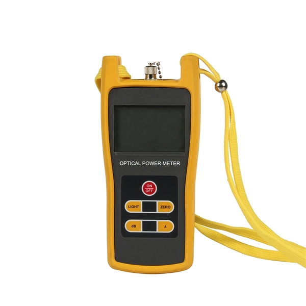
The max insertion loss of a fiber patch cable is 0. 75 dB (the maximum acceptable value) in the TIA standard. Insertion loss (IL) and return loss (RL) are key performance indicators of fiber optic patch cords. This article explains their concepts, standards, testing methods, and FiberMania's quality assurance workflow to ensure optimal network performance. Fiber optic patch cords are crucial components in. A: Fiber optic loss refers to the reduction in signal strength as it travels through the fiber optic cable. This can be due to various factors, including attenuation, connectors, and splices. Q: How is fiber optic loss measured? A: Fiber optic loss is typically measured using an Optical Loss Test. The estimate, called a "loss budget" is calculated using typical component losses for each part of the cable plant - the fiber, splices and/or connectors. If the measured loss exceed the calculated loss by a significant amount (remembering the inherent uncertainty in all measurements), the system. Insertion loss is usually shortened to IL, and the unit of measurement for insertion loss is dBm. ) in transmission systems. It is the power attenuation of the signal after. At TARLUZ, we specialize in manufacturing high-performance fiber optic patch cords that comply with global industry standards, ensuring optimal signal integrity and long-term stability.
[PDF]

Buyers typically pay a range for fiber optic cable per foot depending on fiber type, jacket, and shielding, plus installation considerations. This guide outlines typical cost ranges and the main drivers behind pricing to help formulate a budget and estimate expenses. Fiber optic patch cords are integral elements in data transmission schemes, serving as interlinks between switches, transceivers, and distribution panels in data centers, optical networks (FTTx), and enterprise rooms. For fiber cable materials only, expect $0. 52 per foot for wholesale bulk purchases, or $1 to $6 per foot at retail. Cost factors include material. Get it 12 May, 2026 2518 in Global Warehouse. Get it 18 May, 2026 Get low-loss fiber patch cables & cords with various connector options that support fiber optic cabling up to 400G. Customized cables available. Whether you're planning a national fiber rollout or sourcing cables for enterprise infrastructure, understanding how fiber optic cable pricing works can help you budget more effectively and make better. Corning offers the most complete line of connectors and factory-terminated cables, from single-fiber cords to high-fiber-count cable assemblies. The Corning Quick Connect program offers a 2-day lead time for our EDGE Uniboot Jumpers, with a 90% delivery guarantee. Corning offers the most complete.
[PDF]
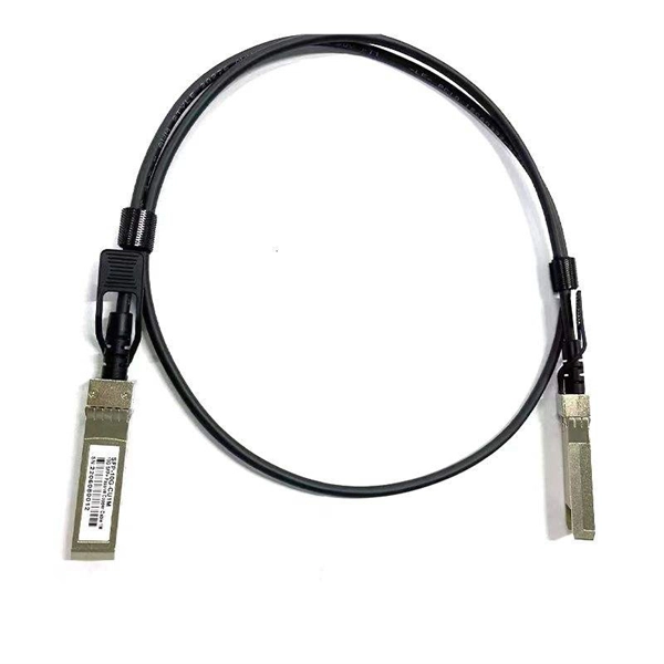
Answer: Ducts and bends choke bulky connectorized heads; long pulls would damage ends; and cumulative connector loss kills your budget. Splice pigtails locally; patch with jumpers on the front. Key. A fiber optic patch cord is a short-length cable (typically 1–10 meters) with pre-terminated connectors on both ends. Its primary function is to connect active network devices (e., switches, routers, transceivers) to passive components (e., patch panels, ODFs) or other devices. They act as the critical link for interconnecting devices like optical switches, servers, and distribution frames. Understanding the various technical. When designing a fiber network, one of the most common questions is: Should you use fiber optic pigtails or patch cords? While they may look similar, their functions are very different—and choosing the wrong one can impact performance and installation efficiency. Without them, even the best optical modules and switches cannot deliver performance. As data rates increase from 10G → 100G → 400G → 800G, patch cables must handle more bandwidth, more density, and stricter. A fiber optic patch cord (fiber jumper) is: Typical applications: A patch cord is the “bridge” that connects two fiber devices and lets them talk to each other. ZION Communication supplies both standard patch cords and custom assemblies to match your equipment, distance, and installation.
[PDF]
The NEC explicitly states that conductive optical fiber cables are not allowed to occupy the same cable tray or raceway as the aforementioned electrical conductors. The key difference here is safety. Nonconductive Optical Fiber Cables: These are typically indoor/outdoor rated fiber cables. This includes conductors for electric light, power, Class 1, non-power-limited. Maintaining proper separation between power, data, and limited energy cabling is foundational to system performance, safety, and code compliance. Separation isn't just an EMI precaution — it protects signaling, reduces rework, and ensures pathways meet inspection expectations across risers. Informational Note: 1 method of defining a cable that is low-smoke producing cable and fire-resistant cable is that the cable exhibits a maximum peak optical density of 0. 50 or less, an average optical density of 0. 52 m) or less when tested. Optical fiber cables shall be permitted to be installed in metal or listed nonmetallic cable tray systems. The previous requirements of 770. Most fiber cables are non-conductive so they can be placed alongside high voltage cables without any special insulation. cable installation must meet the NEC and local building code. Properly fiber rated fiber cables can use the same cable.
[PDF]
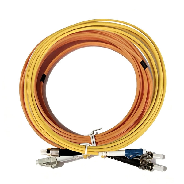
A Mode Conditioning Patch Cord (MCPC) is a specialized fiber patch cord designed to control the launch condition of light from a single-mode transmitter into a multimode fiber. Fiber optic cables primarily come in two types: Multimode Fiber (MMF): Has a larger core, allowing multiple light modes (paths) to travel. It's designed for short-distance, high-bandwidth applications within buildings or campuses. Common types are OM1, OM2, OM3, and OM4. Its primary purpose is to reduce differential mode delay (DMD) and prevent bandwidth limitation when legacy multimode. FS offers OM1 & OM2 mode conditioning fiber optic patch cables (MCP) in any connector & cable length, optimal for eliminating differential mode delay effects. This document describes the installation and use of the mode-conditioning patch cords listed in Table 1. 3z-compliant optical fiber assembly consisting of a single-mode fiber permanently coupled off-center to a 62. 5/125) fiber optic cable by offsetting the Singlemode Laser launch from the.
[PDF]

This guide covers the essential tools and step-by-step procedures for low-loss fiber optic cable repair. Understanding the causes and types of fiber optic cable damage helps detect issues early and determine when repair is needed. Construction Activities: Accidental damage during construction. Step1 : Identify the optical cabinet and network operating center, and find the fiber optic splitter. Step 2: Identify the splitter number. Step 4: Find the optical fiber port and cable sequence that leads to the user. 2) The. This complete guide covers everything from identifying causes of failure to advanced repair techniques, drawing on the latest industry standards and innovations. Whether you're a network technician, IT professional, or telecom operator, you'll find practical steps, tools, and tips to restore. If you accidentally break a fiber optic patch cord in your server room or in any of your switch gear, now you can repair it on the spot and get back up and running in minutes. Adhering to precise methodologies, we can mend impaired cables. By understanding these key elements and following the outlined steps, you can effectively repair fiber optic cables and maintain the high-performance network necessary for today's demanding communication needs. When it comes to ensuring nice network experiences for users, the condition of a fiber.
[PDF]
Stripping and preparing fibre optic cables for termination is a critical step in the installation and maintenance of fibre optic networks. Properly stripping the cable and preparing the fibre ends ensures a clean and secure connection, leading to optimal signal transmission and. If the fiber cracks in a cable assembly, the connection is weakened or lost. Your cable assembly house could face repairing or replacing connectors in the field, which could be exceedingly costly for your company. This article offers multiple tips and best-practice techniques to implement Above is. Once the fiber is cut, the cable moves to a new step of the assembly line, the preparation of the fiber for connectorization. As the phase that comes before, preparing the fiber for connectorization is a part of the manufacturing process, that has some specifications to it. The cable gets to this. The fibers need to have connectors fitted before they can attach to other equipment. In order to terminate a Fiber Optic cable, the appropriate connector must be determined. Various. At the heart of any robust fiber optic network lies a crucial process: Preparing a fiber cable for termination of a connector or splice. When the connector is subjected to stress or temperature.
[PDF]

While nonarmored fiber optic cables don't require grounding due to their nonconductive properties, grounding is crucial when using armored fiber optic cables. Therefore, it is important to build a lightning protection system for fiber optic cables. How to Protect Fiber Optic Cable From Lightning? The major purpose of lightning protection systems is to conduct the high current lightning discharges safely into the Earth/ground. There are two main lightning. Fiber optic cable transmits data as light through glass or plastic strands, which means the fiber core itself carries no electrical current and requires no grounding. However, this does not mean every fiber optic installation is exempt from grounding requirements. Lightning-induced surges can travel through power lines, telecommunication lines, or nearby metallic structures and pose a. There are two main lightning protection grounding solutions in fiber networks, namely intermediate grounding and terminal grounding. These solutions use two ways of grounding for optical cable links both in domestic and foreign standards. However, because fiber optic cable has strengthened core, especially the direct-buried fiber optic cable has armoring layer.
[PDF]
Corning's ClearCurve bend-improved single-mode fibers provide lower cost, superior installation speed and efficiency, and greater successful installations. 15dB ultra low IL fiber optic cable is less attenuation when bent or twisted compared with traditional bend insensitive fiber cables and this will make the installation and maintenance of the fiber optic cables more efficient. Their market growth is directly tied to the expansion of high-speed internet access and innovative data transmission methods. The global fiber optic cable market is. Gain in-depth insights into Bend Insensitive Fiber Optic Cable Market, projected to surge from $ 1. 5 Bn by 2033, expanding at a CAGR of 7. Explore detailed market trends, growth drivers, and opportunities. 5 USD Million in 2024. The Bend Insensitive Fiber Optic Cable Market CAGR (growth rate) is expected. GL FIBER focuses on optical fiber OEM production services, and is committed to providing customers with brand customization, personalized packaging design, optimal cable structure design, and the best packaging design for international container transportation. GL FIBER® provides the whole series.
[PDF]
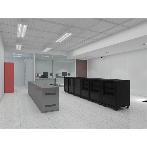
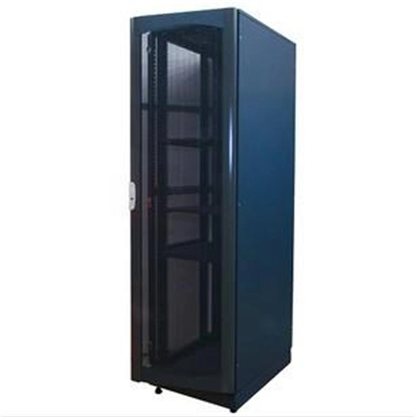
Please view our full RLH price list and contact us at info@fiberopticlink. com if you have any questions or special project needs. A Fiber Optic Patch Panel, also known as an Optical Distribution Frame (ODF) or fiber termination enclosure, is a centralized hardware unit designed to manage, protect, and organize fiber optic cable connections. In an era where data speeds and network reliability are non-negotiable, the patch. fiber optic patch panel, odf, optical distribution frame, fiber distribution panel, rack mount fiber patch panel, wall mount odf, fiber termination box, 1u fiber patch panel, 24 port fiber patch panel, 48 port fiber patch panel, outdoor fiber patch panel, fiber optic odf, sliding patch panel The. Q1: What is the difference between an ODF and a patch panel? An ODF is the entire frame or cabinet managing fiber connections, while a patch panel is a modular unit inside the ODF for cross-connecting fibers. Q2: How many fibers can an ODF handle? It depends on the ODF type; rack-mount units can. ODF is used in the terminal access link of FTTH system. It is a device that splices, distributes, and splits optical fibers and provides protection and management of optical fibers. Belden offers several Fiber Patching Systems. Full patching platforms include FX ECX for LAN environments, FX UHD for high-density fiber channels and the DCX System used primarily in data centers where high amounts of fiber connections and density are the key requirements, as in optical.
[PDF]
Yes, single-mode fiber can transmit and receive data simultaneously. There are two ways to achieve this. We use wavelength division multiplexers (WDM Transceivers) to use this method. The single-mode optical fiber is designed and engineered to carry one single light mode in a minimal core diameter. This type of fiber is used for transmitting signals over long distances. It is specified as the best for especially long-distance applications than multimode fiber. Modes are the possible solutions of the Helmholtz equation for waves, which is obtained by combining. A single-mode fiber optic cable is an optical fiber designed to propagate light signals over long distances with minimal attenuation. It comprises one glass or plastic fiber and features a tiny core of about 8-10 microns in diameter. This small core permits only one light mode to propagate through. For a long time, fiber optic communication required two strands of fiber to accomplish full-duplex transmission—one strand for transmitting and the other for receiving. The core of the fiber is made of a highly transparent material, which allows the light to travel through it with minimal attenuation or loss of signal. This saves space and money. Dual fiber modules use two fibers.
[PDF]

Even when a network is designed correctly, real-world conditions—fiber handling, connector cleanliness, splices, environmental stress, and aging—can gradually increase attenuation or introduce reflections and interference. Fiber optic patch cords are often treated as low-risk consumables, yet a large percentage of optical link failures originate at the patch cord level. Unlike backbone cables, patch cords are frequently connected, disconnected, bent, and handled by technicians, making them the most vulnerable. Optical attenuation is the gradual loss of flux (light intensity) as an optical signal travels through a fiber. Measured in decibels (dB), it's the logarithmic ratio of the output power to the input power. Every network has a "loss budget". Field guide for diagnosing high fiber optic attenuation. Learn to use the OTDR to identify contamination, micro-bends, and poor splices, ensuring your 400G network links remain within budget. This article explains practical, engineering-focused ways to mitigate signal. This measurement helps determine the efficiency of a fiber optic system. Several factors contribute to signal attenuation. These include absorption, scattering, and bending losses. Each factor plays a significant role in the overall performance of a network. Whether you're a network engineer, IT manager, or service provider, understanding these challenges and how to address them is critical for maintaining high-performance, reliable.
[PDF]