
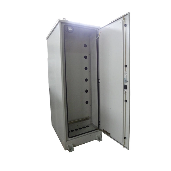
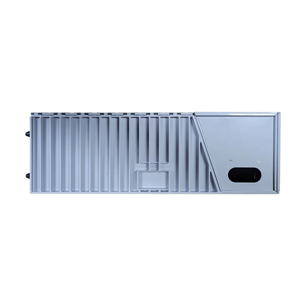
Multi-energy complementary systems combine communication power, photovoltaic generation, and energy storage within telecom cabinets. Featuring lithium-ion batteries, integrated thermal management, and smart BMS technology, these cabinets are perfect for grid-tied, off-grid, and microgrid applications. Explore reliable, and IEC-compliant energy storage systems designed for renewable integration, peak shaving, and backup power. Beyond mechanical protection, these enclosures serve as the. By evaluating the advantages and limitations of different energy-storage technologies, the potential value and application prospects of each in future energy systems are revealed, providing a scientific basis for the selection and promotion of energy-storage technologies. Engineers achieve higher energy efficiency by. A battery energy storage cabinet, in the context of communication sites, refers to an integrated solution that provides batteries, thermal, and electrical distribution, along with monitoring capabilities, housed in a compact cabinet. These energy storage solutions, housed in an outdoor cabinet. An energy storage battery cabinet is more than just a metal box—it's a lifeline for batteries. But without reliable cooling, performance drops and costs rise. An energy storage battery cabinet is a secure, compact enclosure designed to house and protect battery systems used for.
[PDF]
It emphasizes the importance of considering mechanical and environmental aspects, referring to the IEC 60794-2 series for technical specifications. The document details the characteristics of optical fibers and cables, including transmission, microbending and macrobending. Nowadays, optical communications are the most requested and preferred telecommunication technology, due to its large bandwidth and low propagation attenuation, when compared with the electric transmission lines. Besides these advantages, the use of optical fibers often represents for the telecom. As environments are becoming increasingly harsh, the ability of optical fiber cable to withstand such environments is of the utmost importance to outside plant users. Laboratory accelerated aging environments have long been used as a measure to predict field performance of optical fiber and cables'. This study investigates the strain transfer mechanism for different types of fiber optic cables while embedded in concrete cubes, sustaining a boundary condition which features a displacement discontinuity. The strain transfer mechanisms for different cables are compared under increasing strain. This document outlines the recommendations for single-mode optical fiber cables used in telecommunication networks within buildings, focusing on their mechanical and environmental characteristics. It specifies that these cables must comply with standards such as ITU-T G.
[PDF]

This guide explains how to make 90° bends, vertical bends, tees, and offsets in wire mesh cable trays safely and professionally. Horizontal 90° Bend (Flat Bend) 2. Tee (T-Junction) Bend 4. Since the jaws of the bolt cutter drags a layer of zinc across the cut end and forms a protective layer. When a wire cable tray is cut, the fact that a. Wire mesh cable trays are widely used because of their flexibility and easy on-site modification. Unlike perforated trays, bends can be created directly at site without expensive fittings. Great if you are new or just forgot how to do it, this easy to follow guide makes it so simple. more The Easy Guide to. This involves a few essential steps to ensure a successful bending process. The first step in preparing the. The method for producing bridge bend elbows is as follows: Take a 90-degree cable tray bend elbow as an example, and apply the same principles for 45-degree bends accordingly. The length of the bottom side (bottom diagonal) after bending the cable tray should be equal to the width of the cable. OTHER THAN 90 ̊ JUNCTIONS Use this guide to learn the most effective installation practices when installing Cablofil tray. Each example of bends and tee's clearly illustrate proper tray cutting combined with recommended usage of Cablofil accessories. Engineers and contractors in North America and.
[PDF]
One key aspect of this progression is the advent and evolution of transceivers, specifically SFP, SFP+, SFP28, QSFP+, and QSFP28. Let's delve into each of these technologies to understand their specifications, differences, and applications. A Cisco compatible SFP list 2026 represents a validated inventory of optical transceivers that utilize Multi-Source Agreement (MSA) standards to provide identical functionality to Cisco Original Brand (OB) optics. Deploying these modules allows network architects to reclaim up to 80% of their. —— Explosive Growth of 800G/1. 6T Technologies, Scene-Based Selection + Finisar Original Solutions in One Stop In 2026, driven by AI computing power, optical modules have entered a critical era of rate iteration, technological restructuring, and scenario segmentation. 800G has become the mainstream. Choosing the right Small Form-factor Pluggable (SFP) transceiver is critical for network engineers and procurement specialists aiming to optimize performance, cost, and reliability. This SFP buying guide offers a detailed technical comparison, real-world deployment insights, and practical selection. ity with compelling economics. Our ONE Network platform simplifies management of Cambium Networks' wired and wireless broadband and network edge technologies. Our customers can f iness rather than the network. We mak. SFP+ 10G ZR is designed for stable 80km single-mode transmission where standard 10G optics fail.
[PDF]