Learn how to safely wire a single-pole (one way) light switch in this beginner-friendly tutorial. Whether you're replacing an old switch or doing your first DIY electrical project, this guide will walk you through every step — no experience needed!. more. This page contains wiring diagrams for household light switches and includes: a switch loop, single-pole switches, light dimmer, and a few choices for wiring an outlet/switch combo device. That's because virtually all light switches that control 120-volt fixtures are single-pole switches. Most light switches are also single-throw, which. Summary: Fully explained wiring diagrams and photos show how to wire switches including: single switches, 3-way switches, 4-way switches, and dimmer switches. and Be Sure to Subscribe! Make sure the circuit power has been turned off, and mark the circuit breaker or fuse to indicate that work is. A distribution board or distribution box is where the main power supply is distributed to multiple loads. And all the switching and protective devices are installed in the distribution box. Single Phase Distribution Box generally consists of Double Pole MCBs, Single Pole MCBs, and RCCBs. Wiring a single light switch may seem like a daunting task, but with the right tools, a bit of patience, and this comprehensive guide, you'll be able to tackle this DIY project with confidence. Remember, while this guide provides detailed instructions, always prioritize safety and consult a.
[PDF]
Connect the fiber optic cable: Attach the fiber optic cable's connector to the transceiver module on the switch. Make sure the connector type (e., SC, LC) matches the transceiver module. In addition, fiber cables can transmit data over several kilometers without signal degradation, making them ideal for connecting switches in large campus networks and between different buildings. As they do not emit electromagnetic signals, they're difficult to tap and secure against eavesdropping. Fiber optic cabling is increasingly used to connect network switches and other datacom equipment, especially in long-distance and mission-critical applications. Fiber provides: Increased internet signal bandwidth. Most modern fiber-enabled network switches require an SFP transceiver module. As we speak I just have optic fibre (Community Fibre) connected to my Huawei modem / Linksys Velop which will be connected to a new POE switch (need to identify the best model to be compatible with my optic fibre extension project). The objective is to run 1 or 2 additional optic fibre from the. Choose an SFP module based on the fiber optic cabling that will be connected to the network switches. SFP transceiver modules almost always require two fiber optic cable strands. Even the most advanced optical transceivers can only perform at their peak when paired with properly installed, clean, and precisely managed fiber.
[PDF]
This guide demystifies fiber optic splitters, explaining their design, operating principles, types, key specifications, and real-world applications. Whether you're a network engineer designing a PON (Passive Optical Network) or a homeowner curious about how your fiber connection works. I'm planning to use a TP-Link MC220L transceiver to convert the optical signal to ethernet. This ethernet will then go through a 1 Gbit/s switch, and rout two ethernet cables to each floor. On each floor each ethernet cable will be connected to a router, which will then distribute the internet. DWDM/CWDM is like a two-edged sword. For a small fee (the procurement of the modules and the circulator) you can split/splice one physical fibre optic cable into multiple pairs. The downside is that once you loose your one-and-only fibre link (to a cable-hunting-buck-hoe) then you're in trouble. Fiber optic splitters enable the division of optical signals into multiple paths, allowing information to be distributed to multiple subscribers or devices simultaneously. Understanding the inner workings of fiber optic splitters is crucial for network administrators, technicians, and anyone. The answer is yes, and it's a practice widely used in the industry to distribute signals to multiple destinations without degrading the signal quality significantly. What is Fiber Line.
[PDF]
This guide provides instruction on how to install and configure your MS130R series switch. For more switch installation guides, refer to the switch installation guides section on. This guide provides step-by-step instructions for installing two common types of industrial switches: rack-mount, and DIN-rail switches. Choose the Installation Location: Select an appropriate spot on the DIN rail for mounting. This chapter describes how to start your switch and how to interpret the power-on self-test (POST) that ensures proper operation. No prior experience needed—just follow along and you'll have your switch installed and running in minutes. more In this video you'll see a complete, step-by-step guide to mounting. This typeface indicates command syntax, or represents information as it is displayed on the screen. When you see the word enter in this guide, you must type something, and then press the Return or Enter key. Do not press the Return or Enter key when an instruction simply says type. Here, we explore the four most common installation methods for industrial switches: Desktop installation is the most straightforward approach— placing the switch like a small box directly on a table, control panel surface, or equipment rack without extra fixtures. Simple setup: No tools required.
[PDF]

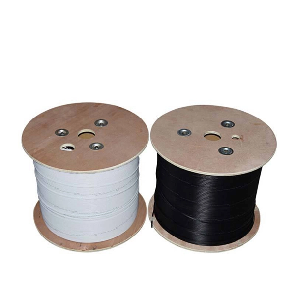
While most pigtails are single-fiber, multi-fiber options exist: Single-fiber: The most common (LC, SC, FC). Multi-fiber: 2, 4, 6, 12, 24, 48, or 72 fibers. Multi-fiber pigtails often come in ribbon format for splicing into high-count cables. Traditional Fusion Splice-On Connectors with pigtails provide factory-polished performance with field-termination convenience within harsh environments. Mass fusion splicing can fuse up to all 12 fibers in one ribbon at once. Mass Fusion Pigtails come with all 12 fibers terminated and a ribbonized. By fiber type, there are single-mode fiber optic pigtail and multimode fiber optic pigtail. And by fiber count, 6 fibers, 12 fibers optic pigtails can be found in the market. Fiber pigtails are used in an estimated 99% of single-mode fiber applications worldwide. Despite this ubiquity, they remain a source of confusion for procurement teams and junior installers alike—especially when it comes to connector type selection, polish type, and the tradeoffs between mechanical. Fiber optic pigtails can be divided into single-mode and multimode fibers. Conversely, multimode fiber pigtails, usually orange, use a 62. 5m to 2m—that has a factory-terminated connector on one end and bare fiber on the other end. The connector end is polished and tested under factory conditions, ensuring low insertion loss and high return loss.
[PDF]
This section includes all PoE enabled Industrial switches available, including managed models and specific application models like vehicle or substation compliant units. Check each product page for other buying options. Shop products from small business brands sold in Amazon's store. Learn more Need help? Industrial-grade PoE switches for demanding. POE Industrial Ethernet units at Plant Technology USA make Power over Ethernet solutions even more efficient and cost effective. Not only are these de. Read more Find the best Industrial Ethernet Equipment for your project. US-based Customer Support. These rugged, fanless platforms support both Gigabit and 10/100 Mbps Ethernet and offer a selection of fixed-fiber, or SFP uplink. We provide a wide range of PoE/PoE+/PoE++ switches with up to 90 W output per port to deliver high-speed data transmission while powering high-power devices over long distances. With an industrial-grade design, our PoE switches provide surge protection of 4 kV per LAN port. Additionally, Smart PoE. In addition to transmitting network data, a PoE Switch has a built-in Power over Ethernet injector to supply up to 100W Power over Ethernet (PoE) to standards-based 802. 3bt compliant devices such as IP cameras, VoIP phones, and wireless access points. When connecting network.
[PDF]

This guide covers the essential tools and step-by-step procedures for low-loss fiber optic cable repair. Understanding the causes and types of fiber optic cable damage helps detect issues early and determine when repair is needed. Construction Activities: Accidental damage during construction. Step1 : Identify the optical cabinet and network operating center, and find the fiber optic splitter. Step 2: Identify the splitter number. Step 4: Find the optical fiber port and cable sequence that leads to the user. 2) The. This complete guide covers everything from identifying causes of failure to advanced repair techniques, drawing on the latest industry standards and innovations. Whether you're a network technician, IT professional, or telecom operator, you'll find practical steps, tools, and tips to restore. If you accidentally break a fiber optic patch cord in your server room or in any of your switch gear, now you can repair it on the spot and get back up and running in minutes. Adhering to precise methodologies, we can mend impaired cables. By understanding these key elements and following the outlined steps, you can effectively repair fiber optic cables and maintain the high-performance network necessary for today's demanding communication needs. When it comes to ensuring nice network experiences for users, the condition of a fiber.
[PDF]
You can run the display arp command to view IP addresses and interfaces of servers directly connected to a switch. Since it is based on arp, it does only work for devices having an ip address in the network segment where you use that feature. So if not used in the management network, it may only be applied with L3 Switches. As far as I know it is not really the case. Ip device tracking can work on L2. Finding the IP address of your network switch is crucial for a variety of tasks, from configuring its settings to troubleshooting network connectivity issues. While it might seem like a technical hurdle, several straightforward methods can help you uncover this essential piece of information. This guide will go over how to find the IP address of the M4300 & M4250 and how to access the web interface of the switch. VLAN 1 of the switch is configured by default to receive DHCP. VLAN 1 is configured by. Is there a command that I can use through Putty to figure out the IP new IP address of the switch? Thank you! Edit: The switch is still isolated and is not connected to anything other than the workstation that I am using to configure it. Just hook back up to the COM port and look. Network switches are integral components of modern computer networks, facilitating efficient data transmission and connectivity among multiple devices. The INTERFACE field displays switch.
[PDF]

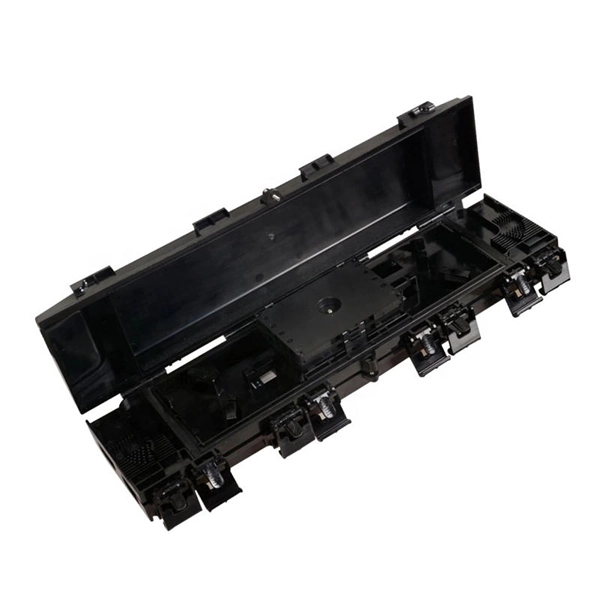
Learn how to install a fiber optic termination box step-by-step for FTTH projects. Covers mounting, splicing, routing, labeling, and testing for indoor/outdoor use. Installing a fiber optic termination box is one of those jobs that looks simple on paper, but it's easy to do poorly in the field. If you do not have relevant experience and skills, it is recommended to ask a professional to install it. Preparations: Before installation. How to install the FTTH terminal box? - YouTube This kind of box are used in the end termination or residential building sand villas, to fix and splice with pigtails, can be installed on the wall. When it comes to ONT installation, you've got two main options: Indoor ONTs are installed inside your home, typically in a utility room, basement or another centralized spot. Both options have their advantages, and the choice. A fiber termination box is the standard instrument used in fiber optic networks to connect, secure, and protect optical fibers at the terminating point. To install a junction box correctly, choose a box that matches the wiring method and environment, mount it securely, bring cables in.
[PDF]
A neat, well-organized subpanel bundles wires to conserve space and improve access. Ideally, wire groups are installed in layers and wires are bent at right angles to buses or breakers. Label short sheathing sections (slugs) to indicate which circuits wires serve. We cover everything from separating color-coded wires and securing them with ties to. Discover 7 DIY tips to organize your electrical panel for improved safety, easier troubleshooting, and efficient maintenance. Prevent hazards while making your home's electrical system more manageable. A disorganized electrical panel isn't just an eyesore—it's a safety hazard and troubleshooting. According to NEC (National Electric Code: Article 1 00-Definitions), a Main Panel (also known as Panelboard, load center, breaker box and distribution board etc. ) is a cabinet or cutout box which contains on controlling and protective devices (such as circuit breakers, fuses, switches etc. ) used to. Welcome to this live training session! ⚡ In today's tutorial, I'll be demonstrating how to arrange cables neatly inside a distribution bo. more See what others said about this video while it was live. If you're struggling with unsightly cords hanging around your cabinets, worry not! In this guide, we'll explore practical strategies to conceal those wires effectively. Before starting the process of.
[PDF]
The global protective relay market size was worth more than USD 2. 82 billion in 2025 and is poised to witness a CAGR of over 5. 5%, crossing USD 4. 82 billion revenue by 2035, fueled by rising integration of digitalization & IoT in protective relay. The global market for Protection Relays was valued at US$ million in the year 2024 and is projected to reach a revised size of US$ million by 2031, growing at a CAGR of %during the forecast period. A protection relay is a smart device that receives inputs, compares them to set points, and provides. The Protective Relay Market was valued at USD 3. 9% through 2024 to 2030, reaching nearly USD 3. 4%, according to Strategic Market Research. Protective relays are essential components of modern power systems. The Protection Relays Market encompasses the design, manufacturing, and deployment of electromechanical, solid-state, and digital relays that monitor electrical systems for faults or abnormal conditions and initiate protective actions.
[PDF]
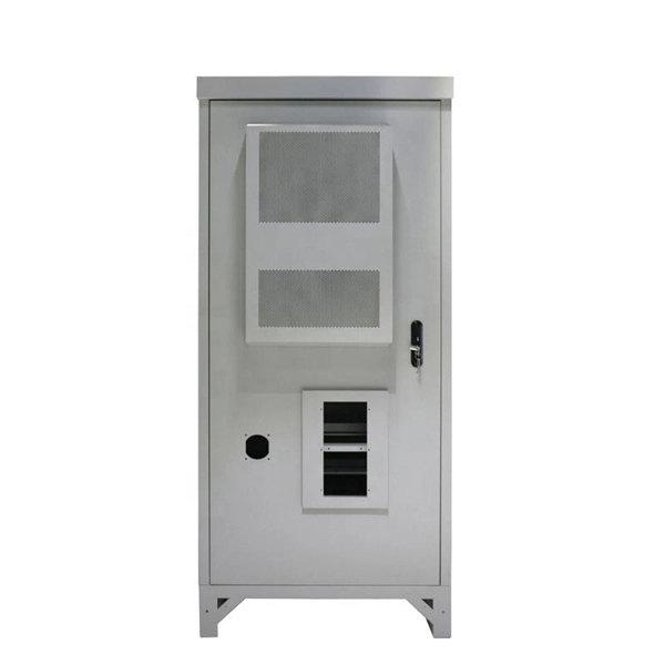
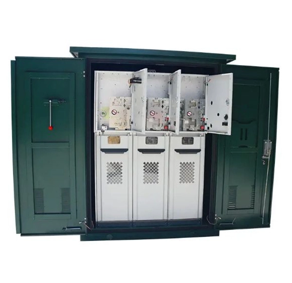
This video shows real on-site footage of electrical installation, demonstrating safe and standardized wiring methods used by professionals. more Learn how to wire a distribution box step by step! This video shows real on-site footage of. Understanding the wiring diagram of an electrical panel box is essential for electricians and homeowners alike, as it allows them to troubleshoot any electrical issues, carry out repairs, or make additions to the system. The electrical panel box wiring diagram provides a visual representation of. A distribution box, also known as an electrical distribution board, is a critical component in electrical systems. It serves as a central point for distributing electricity to various circuits in a building or facility. This section will explain its function, types, and the importance of correct. Understanding how to safely set up the main connections of a home's power distribution system is essential for ensuring reliable and secure operation. A correct installation process minimizes the risk of electrical faults and increases the longevity of your setup. Proper knowledge is crucial for. Material preparation: Prepare the required circuit breakers, wires, wiring ties and other materials, and ensure that they meet the design drawings and installation requirements. Whether you're an electrician or a DIY enthusiast, this guide will help you understand the basics of home electrical distribution. What is Distribution Board? Distribution board.
[PDF]
We calculate cable tray weight using the formula: Volume × Material Density. The calculation accounts for side rails, rungs, and cross-bars. Find the volume of the cable tray: This depends on the dimensions (width, height, thickness) and length of the tray. Multiply the volume by the material density: This gives you the total weight. Now, let's look at the specifics of Cable Tray Weight Calculation for each tray type. Channel trays are. The calculation of cable tray weight relies on the following formula: Weight (kg) = Material Density (kg/m³) × Total Volume (m³) To apply this formula, you need: Material type profoundly influences tray weight and suitability. 00 for bare tray weight. Used only when cover is selected. Used to estimate joints/couplers. Set to zero if unknown. Typical 200–300 mm spacing. rung bar. Height of the Cable Tray You Have: mm Weight Capacity of the Cable Tray You Have: kg/m RESULTS Total dia of all cables: 0. 00kg/m Width of all cables: 0. 00mm YOUR SELECTION ANALYSIS WIDTH CHECK: HEIGHT CHECK: WEIGHT CHECK: REMAINING CABLE. Values are applicable to all resin systems, where possible.
[PDF]
Step1 : Identify the optical cabinet and network operating center, and find the fiber optic splitter. Step 5: Patching from the splitter port to the user. Fiber optic patch cords must be installed correctly to ensure best network performance, reduce signal loss, and protect the sensitive fibers. Whether you're connecting a data center, a corporate network, or a high-density fiber infrastructure, correct installation methods are essential. Yingda. You can put in a fibre patch cord at home. You just need to follow easy steps and be careful. Planning helps you pick the right cord for your network. Be gentle when you handle the cord. Fibre patch cords last longer and are tougher than. This article will guide you through the necessary tools, materials, and methods on how to connect fiber optic cables effectively, ensuring you achieve optimal performance from your fiber optic network. Have a network installation project? Fiber Optic Cables: The primary medium for your connections. NS Comm provides enterprise-grade fiber optic patch cables engineered for maximum reliability and low-loss performance. However, proper installation techniques are essential to unlock their full potential. This guide will help you understand fiber construction, installation steps, real attenuation. Correct patch-cord installation is essential for maintaining low insertion loss, stable return loss, and long-term reliability in both indoor and outdoor fiber networks.
[PDF]
This Cable Sizing Calculator can calculate minimum active, neutral, and earth cable sizes in compliance with the international standard IEC 60364-5-52. It covers all cable types, installation methods, and correction factors in the standards. This guide provides a detailed explanation of cable sizing, including formulas, examples, and tips to help you make accurate decisions for any project. The correct cable size ensures: Safety: Prevents overheating and potential fire hazards. Efficiency: Reduces energy losses due to resistance. Professional electrical wire sizing tool based on National Electrical Code (NEC) standards. Calculate proper wire gauge, voltage drop, and ampacity for safe electrical installations. Input your electrical parameters to get accurate wire size. The calculation follows IEC 60364-5-52 and BS 7671 standards. Selecting the correct conductor cross-sectional area (mm²) is fundamental to electrical safety and system performance. Undersized cables can lead to: Energy inefficiency: Higher I²R losses increasing operational costs. You can estimate. This article examines the sizing of electrical cables (i. cross-sectional area) and its implementation in various international standards. IEC, NEC, BS, etc) and some standards emphasise certain things over others. This cable sizing standard applies to circuits up to.
[PDF]
