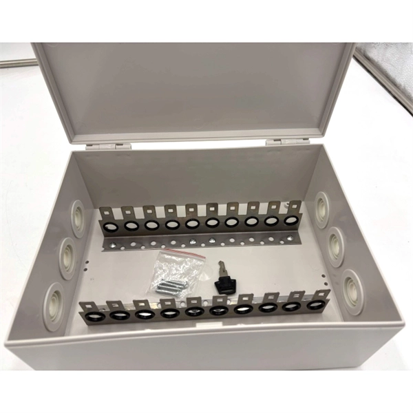
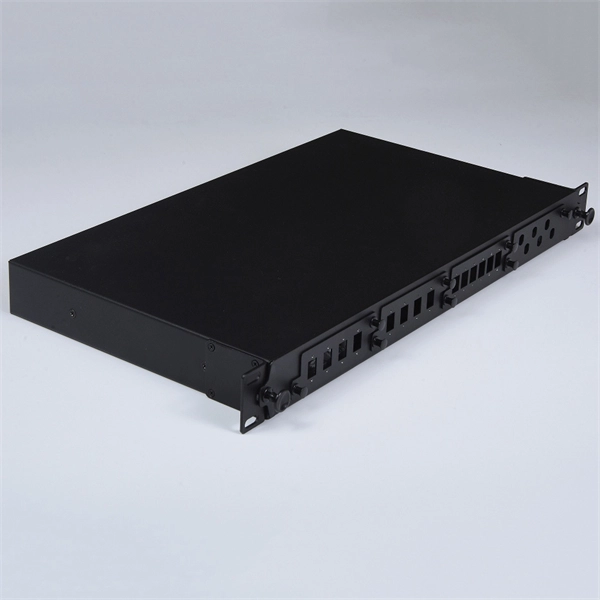
A small server rack should provide long-term value by balancing affordability with durability and functionality. Consider both the initial cost and the long-term benefits when selecting a network rack enclosure. By the end of the week, that blank space held a fully functional network core designed to keep a small professional office online through power cuts, ISP hiccups, and future growth. If you run a home office or manage IT for a small office or business, this summary shows the workflow and gear that. Whether supporting a handful of network switches in a small office or housing rows of servers in a bustling data center, the right network rack protects, organizes, and sustains the technology that drives your business forward. This in-depth guide will give you a 360-degree view of the. Wall-mounted server racks are specifically designed to house network equipment, patch panels, routers, and compact servers in vertical enclosures that mount securely to the wall.
[PDF]

This section provides an overview for server racks as well as their applications and principles. Are you choosing the right server rack manufacturer for your business? Whether you need racks, wall mounted network cabinets, or server cabinets, there are a variety of options available in the United States. Here are the top-ranked server rack companies as of April, 2026: 1. Cyber Power Systems USA. Some of the features include one-piece hinged covers, adjustable vented shelves, vertical cable management, floor mounting holes, integral front waterfall tops, pre-drilled holes, heavy gauge steel frames and vertical mounting-hole patterns. more+ Indoff is estimated to have 200-499 employees. At Rackmount Solutions, we provide rack, cabinet, and physical infrastructure systems designed with safety, protection and adaptability in mind. From open-frame racks to fully enclosed cabinets, our solutions keep equipment secure, organized, and ready for growth. We believe connectivity is the. Discover leading server cabinet manufacturers in the USA: Eabel, Hubbell, and others. Innovative, custom IT infrastructure solutions for diverse needs. They help to organize and secure important equipment by housing them. By selecting a reliable server cabinet manufacturer, you can make sure your equipment gets the best performance which is needed for data centers, networks and IT.
[PDF]
The AC mains high and low voltage cut off circuit I have explained in this article is very easy to build and yet very reliable and accurate. The circuit utilizes a single IC LM 324for the necessary detection and instant.
[PDF]

99 after $25 OFF your total qualifying purchase upon opening a new card. Return this item within 90 days of purchase. Present an elite addition to your outdoor space with this VEVOR PV Combiner Box with Rated Current Fuse Circuit Breaker Lightning Arreste Connector. Lightning strikes pose a critical risk to photovoltaic systems, with 23% of solar farm failures traced to electrical surges according to 2023 NREL data. For engineers and project managers, selecting the right photovoltaic combiner box with integrated lightning protection isn't just optional – it's. A clear wiring diagram helps installers understand the flow of current from each string to the main DC bus, making the system safer and easier to maintain. For systems with three or more DC strings, using a solar combiner box is recommended according to international PV safety standards such as IEC. PV combiner box function: PV combiner box tidied up connection and confluence of photovoltaic modules. It is used to reduce the connection of the photovoltaic array to the inverter and optimize the system structure. Make it easy to cut off the circuit in maintenance and reduce the scope of the power. Pay $44. EKDB-PV4/1-M IP65 DC string box is designed for 4 string PV system, for surge protection and over-load protection at solar DC side.
[PDF]

Are the protection parameters set correctly (trip value, trip time)? Is the assigned protection function blocked? Is the protection function´s trip signal routed to the Trip-Manager of the correct switchgear? Is the trip signal of the switchgear . Are the protection parameters set correctly (trip value, trip time)? Is the assigned protection function blocked? Is the protection function´s trip signal routed to the Trip-Manager of the correct switchgear? Is the trip signal of the switchgear . Master trip relay or lockout relay, also known by ANSI code 86, holds a significant position as an intermediator between the protection relay and control points, even though it is not self-equipped with fault sensing capabilities. The master trip relay can operate as a hub of multiple protection. Since protection relays can be expensive, it is not advisable to connect them directly to the trip coil. if the fault detected by any of the protection relay means at the same time the protection relay trips the associated circuit breaker through the mater tripping relay circuits. Master trip relay is not a monitoring relay. It. After first start-up of the protective device there is a pending trip. Two red LEDs are illuminated at the front of the HMI. It typically refers to the time duration taken a.
[PDF]

Overview The Power System Relay Protection Worker Training and Assessment Platform is developed and manufactured according to the "People's Republic of China Vocational Skill Appraisal Standards • Power Industry (Relay Protection)" and with reference to the relay. I. The participant will learn the basics of distribution protection combined with hands-on, realistic training on actual relays. Laboratory exercises will cover proper relay maintenance, specific. {{$pageCtrl. description}}. Adopting the IEC 61850 standard changes the professional journey of relay technicians. Digital substations require them to develop a keen understanding of IED (Intelligent Electronic Device) communications over Ethernet and grow expertise in virtual protection and control environments. The. Embark on a transformative journey with our Global Certification in Power System Protection course. Dive into key topics such as relay protection, fault analysis, and system stability to enhance your expertise in safeguarding power systems. Gain actionable insights to navigate the complexities of. Our utility relay technician training programs are designed to improve the skills and knowledge of your team through company-specific solutions. Utility technicians play a vital role in protecting power system equipment and the plant as a whole. With FCS's relay technician training, we.
[PDF]
In, a protective relay is a device designed to trip a when a is detected. The first protective relays were electromagnetic devices, relying on coils operating on moving parts to provide detection of abnormal operating conditions such as over-current,, reverse flow, over-frequency, and under-frequency.
[PDF]
Start by examining the plastic cover closely to identify any tabs or locking mechanisms that may be holding it in place. This robust enclosure houses either the main service disconnect or a sub-panel, acting as a control point for electricity distribution to the property or a dedicated outdoor system like a pool or workshop. Gaining access to the panel's interior is usually necessary for simple tasks like resetting a. Opening electrical boxes outside can be a tricky endeavor. Without the proper tools, knowledge, and safety measures, it can also be dangerous. However, with a few simple steps, you can open an outdoor electrical box safely and efficiently. This is how you can open them to have access to the plug-ins. Once you've loosened the. This guide will explore the steps and considerations for safely and effectively punching out a plastic electrical box. Ensure the wires are not powered before starting work. Flat-head screwdriver, electrical pliers, hammer, and a suitable meter or tester. Locate. Before you attempt to open an outdoor breaker box, it's crucial to prioritize your safety. Here is a set of guidelines to ensure you undertake this task without any hazards: Confirm power is disconnected to the unit by turning off the main breaker or disconnecting the main fuse.
[PDF]
Locate the breaker panel, which looks like a large metal box mounted on the wall. Open the panel and look for a switch that's facing the opposite direction from the others. Turn the switch to “Off” and then “On. ” Contact an electrician if your breaker keeps tripping. Yes, in most cases, you can safely turn on a circuit breaker yourself, provided it has merely tripped due to an overload or a minor fault. However, if a breaker repeatedly trips or if you suspect a more serious electrical issue, it's crucial to consult a qualified electrician. Dealing with a. This wikiHow article will teach you how to safely find and flip a tripped breaker, restoring your power. Turn the switch to. This guide's handy whether you're looking at a circuit breaker for the first time or an electrical veteran looking for a better way to explain what to do if the breaker trips. Why Do Breakers Trip? Circuit breakers trip when there's too much current (aka “ overcurrent “) on the circuit, and it. To reset a tripped breaker, switch it entirely OFF first, then back to the ON position. You don't need to turn off the main power to reset individual breakers. Continuously identify and. Mr. Electric recommends these steps to restore power safely when your circuit breaker trips. Turn off and unplug devices on the affected circuit.
[PDF]

The key lies in their fully sealed design, acting as a “protective shield” for the cabinet, effectively preventing dust, salt spray, and high-temperature air from entering. So, how can this more reliable cooling solution become more economical to support large-scale 5G. ESTEL designs each Telecom Power System and outdoor telecom cabinet to adapt to these challenges. You get reliable performance through robust materials, smart energy management, and advanced engineering. ESTEL's dedication to quality, innovation, and international standards ensures your equipment. With 5G base stations, smart light poles, outdoor communication cabinets and other infrastructures spreading all over urban and rural areas, outdoor telecommunication equipments are facing severe tests such as extreme temperature difference, humidity and rain, and dust intrusion. Traditional. Available in different configurations, Delta OutD cabinets are designed to protect equipment from external threats in all climates from the tropics to the arctic. In addition to traditional cooling methods, Delta's new hybrid cooling options revolutionize the cost structure of thermal management. Featuring a robust steel structure with IP-rated protection, it ensures reliable operation against dust, rain, heat.
[PDF]
Looking for reliable outdoor power solutions in Casablanca? This guide explores top local suppliers, key features to consider, and emerging trends in Morocco's renewable energy sector. Morocco's ambitious renewable energy targets and growing tourism sector make it a hotspot for outdoor power solutions. With 52% of electricity slated to come from renewables by 2030, businesses and adventurers alike need reliable off-grid systems. Whether you're a homeowner, business operator, or outdoor enthusiast, discover how to find the right power supply. Discover Morocco's top solar energy system suppliers, each pioneering a sustainable future with unique, innovative solar solutions. Morocco, with its abundant sunshine, has embraced solar energy as a cornerstone of its renewable energy strategy. As the demand for sustainable and cost-effective. Solar Power Solutions Pvt Ltd is the premier solar company in Morocco. Our comprehensive range of services includes solar installation, solar energy solutions, and. While DIY kits exist, professional services ensure compliance with Morocco's ONEE regulations and proper weatherproofing. One client learned this the hard way—their ungrounded system failed within 6 months during heavy rains. Specializing in renewable energy integration, we've deployed over 120. Discover vast solar energy projects powering Morocco, including large-scale solar farms designed to harness the desert sun efficiently. Transforming water into energy.
[PDF]
Microprocessor-based solid-state digital protection relays now emulate the original devices, as well as providing types of protection and supervision impractical with electromechanical relays.OverviewIn, a protective relay is a device designed to trip a when a is detected. The first protective relays were electromagnetic devices, relying on coils operating on moving par. Electromechanical protective relays operate by either, or. Unlike switching type electromechanical with fixed and usually ill-defined operating voltage thresholds. Electromechanical relays can be classified into several different types as follows: "Armature"-type relays have a pivoted lever supported on a hinge or knife-edge pivot, which carries a moving contact. These relays may.
[PDF]

The K factor (or zero-sequence compensation factor) adjusts the measured impedance for the phase-to-ground fault loop by accounting for the contribution of zero-sequence currents. This compensation is critical because zero-sequence current introduces an offset in the fault impedance. The following Terms are used in protective relaying: 1. Fault Clearing Time 5. Drop Out or Reset value 8. Sealing Relay or holding Relay 10. Hermetically sealed, corrosion resistant metal can. Detail specifications and ordering data appear on the Data Sheet below. NewElec's KA, KB & KC Series relays provide robust and dependable motor protection relays designed to safeguard critical motors in a wide range of industrial applications. Fixed thermal curves (Class 15 Cold - Class 5 Hot) with thermal pre-loading, match the Hot and Cold stall times of the motor during operation. The KA relay is mains powered. The protection and control devices in electrical equipment can be referred to by numbers, with appropriate suffix letters when necessary, according to the functions they perform. These numbers are based on a system that is adopted by a standard for automatic switchgear by Institute of Electrical.
[PDF]
The fault can be located upstream or downstream of the relay's location, allowing appropriate protective devices to be operated inside or outside of the zone of protection.OverviewIn, a protective relay is a device designed to trip a when a is detected. The first protective relays were electromagnetic devices, relying on coils operating on moving par. Electromechanical protective relays operate by either, or. Unlike switching type electromechanical with fixed and usually ill-defined operating voltage thresholds. Electromechanical relays can be classified into several different types as follows: "Armature"-type relays have a pivoted lever supported on a hinge or knife-edge pivot, which carries a moving contact. These relays may.
[PDF]
PC configuration software for Reyrolle products including Reydisp Manager 2, Reydisp Manager 1, and Reydisp Evolution. Doble RTS™ (RTS) is the premier protection testing software system for improving the work of testing relays and managing test records. Process consistency with power and flexibility set RTS software apart, and tremendous automation enables unmatched efficiency, accuracy and productivity. Apply your. Download documents, support information, software, video and audio content. IEC61850 Digital Substation Testing With 15 years experience in IEC61850 digital substation testing, KINGSINE portable relay testers are designed for comprehensive testing in both traditional and digital substations, including MU and IEC61850 compliant IEDs. Protection Relay Test Set/Kit KINGSINE. The commissioning of protection systems is an essential step to ensure the safety, reliability, and operational efficiency of electrical installations. In this context, the testing of protection relays and IEDs (Intelligent Electronic Devices) must be carried out with maximum precision, speed, and. A software designed to manage all aspects of protective relay testing using the Megger SMRT and FREJA models of relay testers. Facilitates steamlined and efficient relay protection testing through automation and relay modules. By using one of the over 400 relay templates with relay settings import. Portable at just 15 kg, the FREJA 300 is intended primarily for.
[PDF]