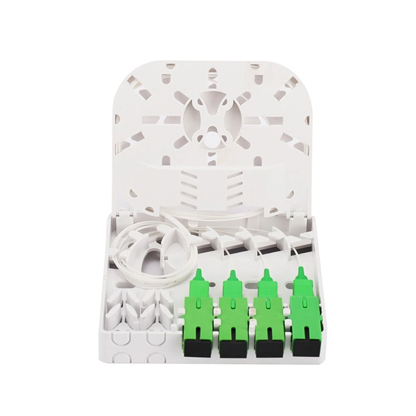
The primary function of a fiber adapter panel is to provide a housing for fiber optic adapters or connectors. These adapters act as the interface between the terminated fiber ends and the active equipment, such as switches, routers, or servers. A fiber patch panel is a mounted enclosure—either rack-mounted or wall-mounted—used to terminate, manage, and interconnect multiple fiber optic cables. It acts as a hub for organizing splices and patch cords, streamlining fiber management and preserving signal integrity. This guide will focus on elucidating the aspects of the fiber patch panel, its accessories, the work done with such a device, and how to. Fiber optic networks are the backbone of fast, reliable internet and modern communications, but even the best fiber cables need the right connectors and patch panels to work efficiently. Connectors are the points where fiber cables link to devices, equipment, or other cables, and using the right. The fiber optic patch panel, also known as the fiber distribution panel, serves as the crucial component of the management of fiber optic cables. Also, the advantage of fiber optic patch panels is to reduce the loss of fiber optic transmission and facilitate engineers to troubleshoot. Serving as the network's centralized junction, it provides secure ports for both incoming and outgoing fibers, streamlining connection.
[PDF]
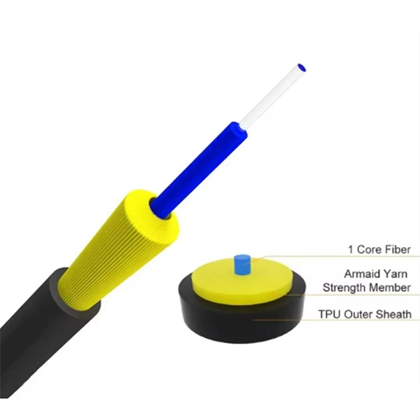
Basic run: 800 ft outdoor fiber drop with aerial installation, minimal trenching, and standard termination. Labor: 12–18 hours; Materials: $1,200; Total: $3,500-$6,000. Homeowners and businesses typically pay for fiber optic cable installation based on distance, conduit needs, and labor. The main cost drivers include material type, run length, trenching or aerial work, and any required permits or inspections. This article provides cost. A simple 1-core FTTH drop cable costs around $0. 13 per foot, while a 288-count optical fiber cable for building backbones can reach $6 per foot or more. Pre-terminated assemblies and patch cables incur higher costs due to factory termination, with prices varying by connector type and the number of. Whether you need singlemode, armored, or indoor plenum, this guide gives you the exact cost per foot of fiber optic cable — including installation — so you can budget without guesswork. Data aggregated from Q1 2026 contractor invoices across Texas, Ohio, and North Carolina. Understanding cost ranges helps buyers budget. Cost of Laying Fiber Optic Cable in the U. The price ranges reflect both ongoing improvements in fiber deployments and regional differences in permitting and crew rates.
[PDF]
The reels are designed for handling fiber cables in temporary installations. It can be stacked, has room on the inside for storing connectors (size up to Probeam Sr. Fiber-optic cables on cable drums are versatile. For any kind of events, e. Trade fairs, sports events, conferences, filmed productions, etc. Fiber optic cables. Fiber optic cable reels are essential tools in the telecommunications and cable installation industries, designed to facilitate the handling, storage, and transportation of fiber optic cables. These reels are specially engineered to meet the precise needs of fiber optic cables, ensuring their. OCC is pleased to introduce the Modular Advanced Reel System (MARS), the industry's first lightweight cable deployment reel system designed specifically for the demanding needs of harsh-environment fiber optic installations. The drums have brakes, fold-in swivel handles, and drums of the. Mobile Cable Reel,Optical Cable Reel, Optical Fiber Take up Reel, Sturdy and Durable Stand, Easy to Grip Handles, Portable Signal Line Reel Black This product has sustainability features recognized by trusted certifications. Made with chemicals safer for human health and the environment.
[PDF]
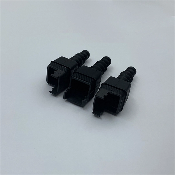
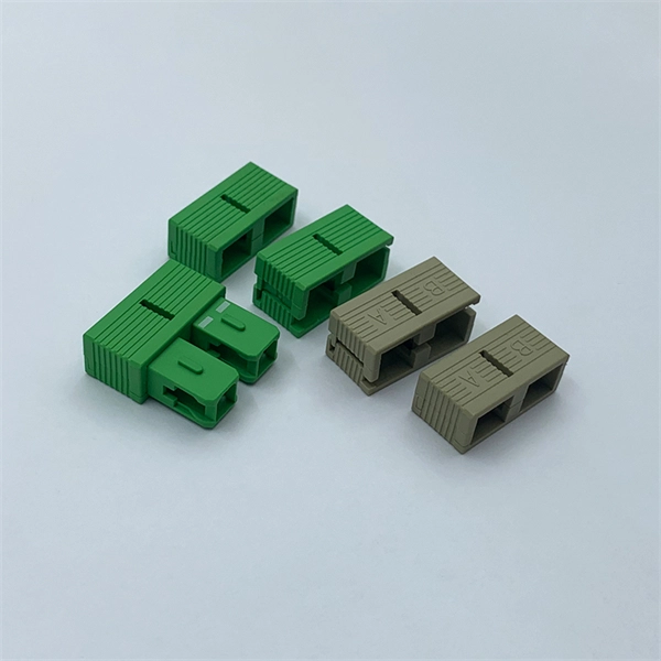
They are the bridge between fiber optic cables in the field and the equipment or patch panels that manage them. By combining factory-installed connectors with spliced bare fiber, pigtails ensure that network installers can create fast, reliable, and cost-effective terminations. Each splice tray includes one or more slots containing fusion, mechanical, or pigtail splices and single mode or modes splicing configurations. Tampering with such splice trays would render the fibers unbent and significantly reduce the network's likelihood of loss or collapse. As a result, they. Fiber pigtails are simple in appearance, yet essential in function. This article will show you what a fiber optic pigtail is. The success of a network in fiber optic cable installation heavily. This is a technology less than a decade old that combines the splice tray, adapter panel, pre-stripped and routed pigtails and splicing consumables required for optical fiber termination in a single compact cassette. In this article, we will examine the factors that have put the exciting new. A fiber optic pigtail is a type of fiber optic cable with only one end that has a factory-terminated connector and the other end exposed as bare fiber. Hence the connector side can be linked to equipment and the other side melted with optical fiber cables. Fiber optic pigtail are utilized to terminate fiber optic.
[PDF]
We analyzed 77 Internet of Energy startups. 2GG, Leap, Bandora Systems, Covert Science, and RESYNC develop 5 top solutions. Learn more in our Global Startup Heat Map!. With the rapid advancement of battery technology and the demand for environmental sustainability, new energy vehicles (NEVs) are becoming more and more popular. This research paper delves into the impact of marketing strategies employed by new energy vehicle companies on consumers' purchase. Under the global trend of green economy and energy conservation, the automotive industry has increasingly shifted towards new energy vehicles (NEVs). This study focused on ORA, a leading NEV brand, and aimed to analyze its marketing strategy using SWOT analysis and the 4Ps marketing theory. The. The first theme is 'Energy Market Characteristics' and deals with the experts' description of energy companies and markets, and ways in which branding has been used in the energy sector. Options for renewable sources, smart tech, and flexible tariffs put control in their hands. The result? Traditional marketing no longer wins attention or trust. The pace of transformation is relentless. Amidst the vast digital landscape, SEO acts as a guiding beacon for renewable energy brands, ensuring that their voices resonate prominently across search engines and online platforms.
[PDF]
Key cost drivers include panel amperage, indoor vs outdoor location, wiring length, and whether a full panel upgrade or rerouting is needed. Your practical guide to smart power solutions for modern buildings Ever walked into a room and flipped a switch without thinking about what makes the lights come on? That's the magic of a well-designed electrical system. Whether you are a seasoned procurement officer or a first-time project manager, understanding the distribution box market is about more. The global market for Distribution Boxes was estimated to be worth US$ million in 2023 and is forecast to a readjusted size of US$ million by 2030 with a CAGR of % during the forecast period 2024-2030. North American market for Distribution Boxes was valued at $ million in 2023 and will reach $. Homeowners typically spend several hundred to several thousand dollars for distribution box work in septic systems, depending on system size, material, and installation complexity. The main cost drivers are the number of boxes, trenching, backfill, and permit requirements. The article outlines cost ranges, per-unit pricing, and practical. In this guide, we will explore the key factors that impact pricing in the industry and help you make informed decisions when selecting a warehousing and distribution service provider that meets your needs and budget. As shown in the chart above, warehousing & distribution services on Clutch are.
[PDF]
There are several diagnostic methods to help troubleshoot fiber optic connectors, and the diagnostic method is to cross-section the fiber optic connector. This technology allows us to actually look inside the fiber optic connector to see defects and pinpoint the cause of. Fiber design and transmission technology have collaboratively evolved to increase bandwidth. Dig-ups dominate! Cablers have very little influence on the majority of causes of cable field failures. While a small percentage, we can examine the “intrinsic” cable failures and what is done to prevent. Connector failure is most frequently the result of a dirty or damaged end-face. Fiber-optic connector: SC type In the connector, the element that holds the fiber and provides the alignment positioning is the ferrule. The. In August of 1999, Boeing Corporation (Boeing) engineers being used on International Space Station flight a defect in the glass fiber (see Figure 1, “Rocket and NASA engineers and managers, Boeing created and reliability of the cable installed in the U. Fiber coupling can be accomplished by fusion splicing.
[PDF]

Buyers typically pay a range for fiber optic cable per foot depending on fiber type, jacket, and shielding, plus installation considerations. This guide outlines typical cost ranges and the main drivers behind pricing to help formulate a budget and estimate expenses. Fiber optic patch cords are integral elements in data transmission schemes, serving as interlinks between switches, transceivers, and distribution panels in data centers, optical networks (FTTx), and enterprise rooms. For fiber cable materials only, expect $0. 52 per foot for wholesale bulk purchases, or $1 to $6 per foot at retail. Cost factors include material. Get it 12 May, 2026 2518 in Global Warehouse. Get it 18 May, 2026 Get low-loss fiber patch cables & cords with various connector options that support fiber optic cabling up to 400G. Customized cables available. Whether you're planning a national fiber rollout or sourcing cables for enterprise infrastructure, understanding how fiber optic cable pricing works can help you budget more effectively and make better. Corning offers the most complete line of connectors and factory-terminated cables, from single-fiber cords to high-fiber-count cable assemblies. The Corning Quick Connect program offers a 2-day lead time for our EDGE Uniboot Jumpers, with a 90% delivery guarantee. Corning offers the most complete.
[PDF]
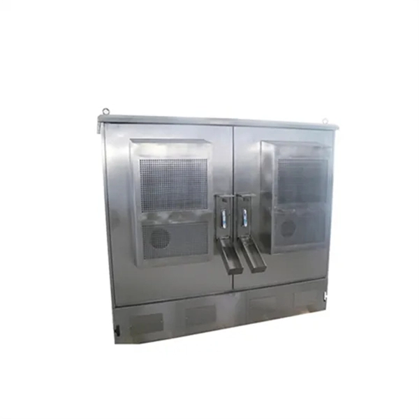
Shop Outdoor Stainless Steel Electrical Enclosure Box Weatherproof Junction Box Meter at best prices at Desertcart Guyana. ✓FREE Delivery Across Guyana. ✓EASY Returns & Exchange. -The bottom shell and surface frame are made of ABS newmaterial,while the transparent cover is made of PC newmaterial,which has characteristics such as good toughness,high strength,good impact resistance,and long service life. -Suitable for various indoor and outdoor places such. There is no review for this item, add the first one. XRM lighting distribution box is a lightweight distribution device indispensable for secondary distribution in various industries. With the improvement of electrical. VERSATILE APPLICATIONS - Perfect for both indoor and outdoor use across various environments. With features like a reinforced lock, thick. They provide a protective enclosure for electrical connections and help to prevent electrical hazards. In this article, we will explore the different types of electrical boxes available and their uses. Junction Boxes: Junction boxes are used to house electrical coections, such as wires or cables. Electrical distribution boxes are used in commercial and residential buildings and are part of the electrical system, also known as switchboards. It integrates power distribution, protection, and monitoring capabilities, and is responsible for distributing power to entire commercial or residential.
[PDF]
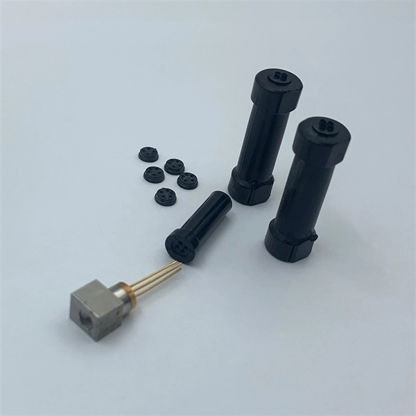
A fiber optic pigtail is a short length of optical fiber —typically 0. 5m to 2m—that has a factory-terminated connector on one end and bare fiber on the other end. The connector end is polished and tested under factory conditions, ensuring low insertion loss and high return loss. They are the bridge between fiber optic cables in the field and the equipment or patch panels that manage them. By combining factory-installed connectors with spliced bare fiber, pigtails ensure that network installers can create. The most urgent stage of the process is, in fact, separating fiber optic pigtail, also known as pigtail fiber or pigtail fiber optic cable. These short, pre-terminated cables play a vital role in terminating and splicing optical fibers, especially in complex fiber infrastructure such as data. Executive Summary: A fiber optic pigtail is one of the most commonly specified yet least understood components in structured cabling. Get the wrong connector type, the wrong polish, or skip proper fusion splicing technique—and you're looking at elevated signal loss, increased back reflection, and a. A fiber pigtail is a short optical fiber cable with a connector pre-installed on one end and a bare fiber on the other. The quality and.
[PDF]
OPGW cable vibration dampers are essential devices designed to reduce aeolian vibration in optical ground wire cables. Whether spiral, Stockbridge 2 or clamp type, these dampers work by absorbing vibration energy, which prevents fretting fatigue and premature breakage of the cable. This article explores the importance of optical cable vibration dampers, their design and functionality, and. IEC describes the Stockbridge damper as a system consisting of a messenger cable with two masses at its ends and a clamp that supports them; this clamp is attached to the conductor or earthwire with the purpose of reduction of the aeolian vibration on the conductor. Sure enough, starting from a. All Rights Reserved | Privacy Policy | Sitemap Vibration Dampers - Conductor vibration induces a relative motion between the clamp and the inertia weights which causes flexure of the steel cable, resulting in dissipation of mechanical energy by friction between the strands of the damper cable. In. The non-slip type vibration damper we provided with particular weight and reasonable shape design,it can produce multi resonant frequencies and effective absorption the different frequencies of vibration. Adopting the helical structure form of installation, it have large adhesion area and evenly. The Spiral Vibration Damper is a motion control product used to dissipate aeolian vibration that may occur on cable spans. PLP transmission.
[PDF]
Its primary purpose is to ensure safe and efficient power distribution while providing protection via fuses or circuit breakers against overloads and short circuits. Distribution boxes are built with durable materials, typically metal or high-grade plastic, designed to endure. Most distribution boxes contain circuit breakers or fuses that function as protective barriers for the connected wiring and electrical devices. These safety components monitor the electrical flow continuously. When electrical problems occur—such as short circuits or excessive power draw—the circuit. Its primary role is to ensure safety, control, and organization. Let's break down its core functions. Centralized Control and Distribution The main function of a Distribution Box is to act as a central hub. The single, thick cable bringing power from the utility company enters this box. Inside. A low voltage distribution box safely manages and protects electrical circuits, ensuring reliable power distribution and enhanced safety in any building. It is commonly used in homes, offices, and industrial settings to control and protect electrical circuits. It helps organize, protect, and control electrical connections in residential, commercial, and industrial electrical systems.
[PDF]
A fiber coupler is a passive optical device that manages the flow of light signals within an optical network. It functions by dividing a single incoming light path into multiple outgoing paths, or by combining light from several input paths into a single output fiber. What are some common uses of fiber couplers in fiber optics, including fiber lasers? What are dichroic couplers and how are they used in fiber amplifiers? What is the principle of evanescent wave coupling? What factors influence the coupling strength and wavelength sensitivity in fiber couplers?. This tab provides a brief explanation of how we determine several key specifications for our 1x2 couplers. This capability is fundamental. Fiber optic coupler is one type of fiber optic component that allows for the redistribution of optical signals. It covers a wide range of fiber optic devices such as optical splitters, optical combiners, and optical couplers. A fiber optic coupler is a device that can distribute the optical signal. Fiber optic couplers are optical devices that connect three or more fiber ends, dividing one input between two or more outputs, or combining two or more inputs into one output. List the types of extrinsic and intrinsic coupling losses. Understand the degree to which fiber alignment and fiber mismatch problems increase system loss. Detail the score-and-break cleaving.
[PDF]

An optical coupler helps split or join light signals in a fiber network. It can take one light signal and send it to two or more places. They do not send signals to the. An Optical Splitter, also known as a beam splitter, is a passive optical device that divides a single input optical signal into two or more output signals. Unlike active devices (which require power), splitters operate without electricity, relying solely on the physics of. You use optical couplers and splitters to split or join signals in fiber networks. For example, optical splitters send light to many output ports. This lets you connect more users to one network terminal. You can also use them to join light from. Optical Distribution Network (ODN) - The physical fibre and optical devices that distribute signals to users in a telecommunications network. The ODN is composed of passive optical components (POS), such as optical fibers, and one or more passive optical splitters. Optical Network Termination (ONT). Functioning as a translator, the ONT converts optical signals from the fiber optic cable into electrical signals that your router and devices can understand. In essence, it serves as the bridge between your internet service provider's (ISP) network and your home network. This type of device plays an important role in passive.
[PDF]
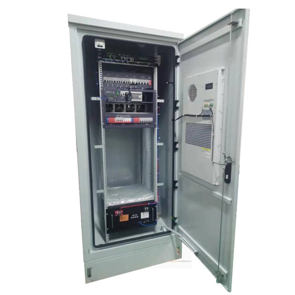
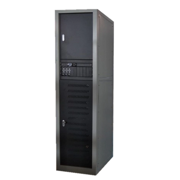
ODF, also known as optical distribution frame or fiber optic patch panel, is a critical device used in optical communication for managing and distributing optical fibers. It is usually a compact and structured framework composed of a steel shell and internal fiber splice tray as the. This complete guide explores everything you need to know about ODFs — from their structure, types, and key components, to installation best practices and modern design trends. Whether you're building a central office, data center, or FTTx distribution network, understanding the right ODF. An Optical Distribution Frame (ODF) is the central hub for fiber splicing, termination, patching, and cable protection in modern optical networks. Mainly used in the junction point between the optical transport networks and the optical transmission equipment, or bet een the optical fiber access networks and the user cable. It serves as a merging point for the optical fibers, where connections are consolidated and routed, thus minimizing signal attenuation. The ODF includes.
[PDF]