An Optical Distribution Frame (ODF) is a dedicated unit designed to organize, terminate, and interconnect fiber optic cables. It brings together fiber splicing, patching, and cable routing in a single structure, while shielding sensitive connectors and splices from mechanical. In the complex architecture of fiber optic networks, the Optical Distribution Frame (ODF) serves as the linchpin for organizing, protecting, and distributing optical signals. Whether in data centers, telecom central offices, or enterprise network rooms, ODFs enable efficient fiber management. Among the many solutions available, the Optical Distribution Frame (ODF) plays a central role in organizing, protecting, and simplifying fiber management in telecom rooms, central offices, and data centers. As data centers, enterprises, telecom operators, and smart-building infrastructures deploy increasingly dense fiber links, ODFs provide the structured. Optical Distribution Frames (ODF) are indispensable components in optical communications networks. They provide efficient fiber optic management, connectivity, and protection. Whether you are building a data center, deploying FTTx networks, or managing the telecom systems, the selection of suitable ODF is very important since the fiber connections are optimized.
[PDF]
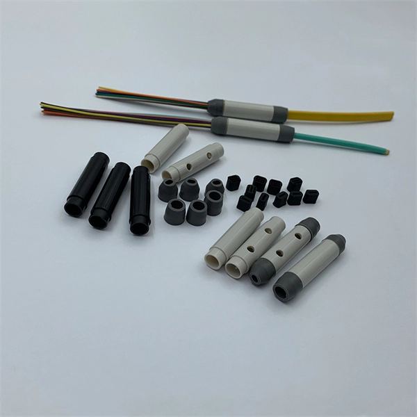
They are suitable for both single-mode and multimode fibers and are available in permanent or reenterable types. In contrast, fusion splicing offers a more robust solution by permanently welding the fiber ends together using an electric arc. The three basic fiber interconnection methods are: de-matable fiber-optic connectors, mechanical splices and fusion splices. De-matable connectors are used in applications where periodic mating and de-mating is required for maintenance, testing, repairs or reconfiguration of a system. The penalty. Auto Mode is the most intuitive and user-friendly splice mode. The fusion splicer automatically detects the fiber type, such as single-mode (SM), multimode (MM), or dispersion-shifted (DS) fibers, and adjusts parameters like arc power and heating time accordingly. Fusion splicing is the most widely used method of splicing as it provides for the lowest loss and least reflectance, as well as providing the strongest and most reliable joint between two fibers. Differences in ibers, equipment, environment. In this guide, you will find a chronological description of the fusion splicing process, the principal technical standards, and answers to the real-life questions network engineers and procurement teams may have. The guide provides the complete workflow, covering safety precautions, tool selection, fiber preparation, fusion operation, quality control, and.
[PDF]

Fusion splicing is the most widely used method of splicing as it provides for the lowest loss and least reflectance, as well as providing the strongest and most reliable joint between two fibers. Virtually all singlemode splices are fusion. There are two main methods of splicing: mechanical splicing and fusion splicing. This blog will delve into the nuances of each method, comparing their costs, labor efficiency, network performance, and more, to help you decide which splicing technique is best suited for your needs. Why splice? Fiber. Fusion splicing is the process of fusing or welding two fibers together usually by an electric arc. Fiber splicing means joining two optical fibers (permanently or temporarily) such that light guided in one fiber and reaching the joint (splice) can be transferred into the second fiber with low insertion loss. Another method of connecting optical fibers is termination or connectorization, which consists of processing the end of a fiber optic bundle so that it can be connected to other fibers or devices through fiber optic. Fiber Optic Cable is a form of modern network cable that has a far greater capacity than electrical communication connections. Splicing is typically required during cable installation, maintenance, or network expansion. The goal is to achieve the lowest possible optical loss (signal.
[PDF]

The LC Simplex to Blunt Single-mode (OS2) Splice-On Pigtail provides a dependable solution for terminating 900µm buffered fiber. This 2-meter assembly features a factory-terminated LC connector that is tested for low insertion loss and reliable performance. Leviton fiber optic pigtail kits are a good solution for mechanical or fusion splicing applications. Available in a range of multimode and single-mode fibers with SC, ST or LC connectors. Economy pigtails offer over a. Traditional Fusion Splice-On Connectors with pigtails provide factory-polished performance with field-termination convenience within harsh environments. Mass fusion splicing can fuse up to all 12 fibers in one ribbon at once. Closet Connector Housing (CCH) pigtailed splice cassettes enable faster field splicing and easy modular management of connectorization within the housing. They are preloaded and prerouted for quick fusion splicing of. Get it 12 May, 2026 108 in Global Warehouse. Get it 18 May, 2026 FS offers single mode & multimode fiber pigtails with tight buffer design for easy fusion or mechanical splicing. Quality assurance by 100% end-face, IL & RL testing. Each strand is terminated on one end and the other end is left blunt so that it can be spliced to your drop cable. Our fiber pigtails come with a partial outer jacket to help protect the tight buffer fibers.
[PDF]
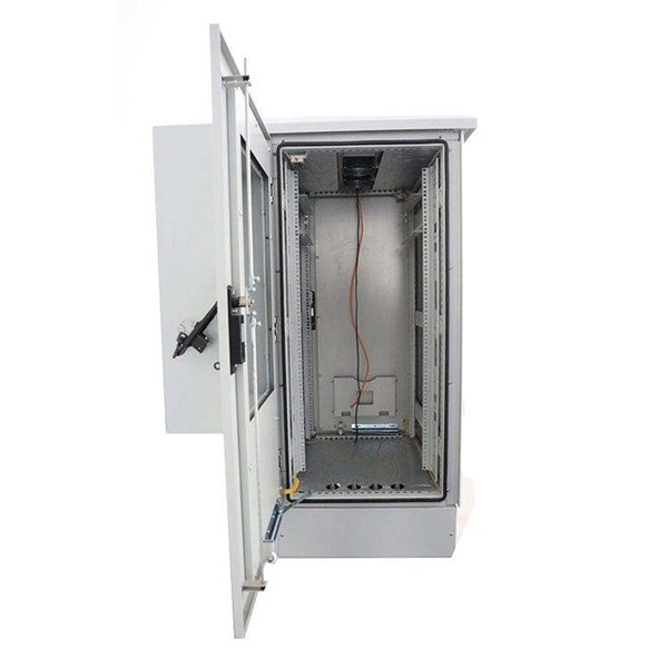
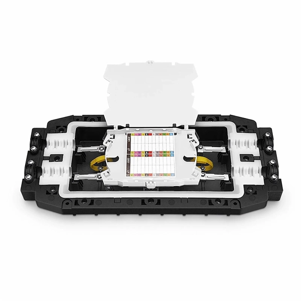
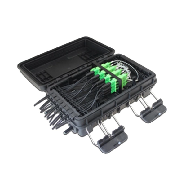
A fiber optic termination box is an enclosure designed to terminate incoming optical fiber cables and distribute optical signals to drop cables or patch cords. It integrates fiber splicing, adapter management, and cable protection in one compact unit. A fiber optic termination box, often called an optical distribution frame (ODF) or fiber patch panel, serves as the endpoint where incoming fibers connect to devices or. A fiber optic termination box is a core component in modern fiber optic networks, providing a secure and organized point for fiber termination, splicing, and distribution. It is widely deployed in FTTH, FTTB, and other access networks to ensure stable signal transmission from backbone cables to end. Fiber termination refers to the process of preparing the end of a fiber optic cable to connect to another fiber, a device, or a network. There are two primary. A Fiber Termination Box, also known as a Fiber Distribution Box, is a crucial component in fiber optic networks. It is a small enclosure that can house and protect the fiber optic cables, splices, and connectors. The fiber termination box. Choosing the right fiber optic terminal box is less about buzzwords and more about matching physics and field reality to your site: where the box will live, how many cores you need now and later, how technicians will access it, and what level of environmental and mechanical protection the network.
[PDF]
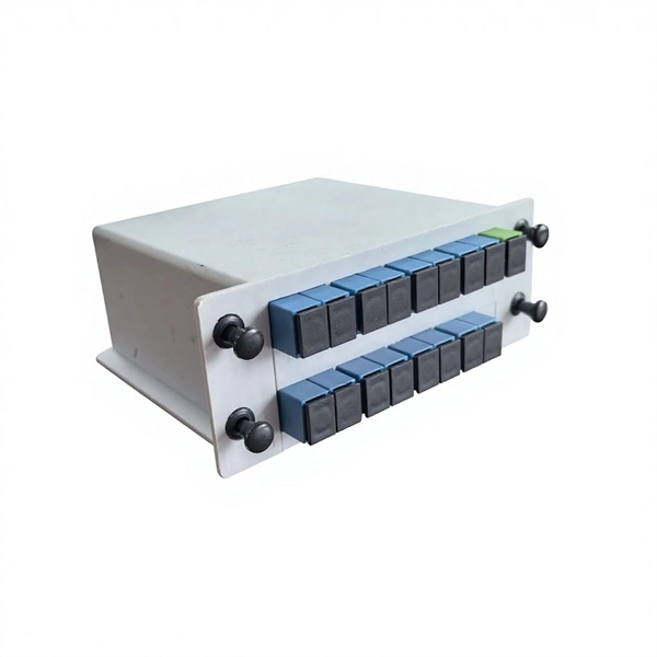
Calculate split loss, excess loss, and terminations for any ratio quickly today. See power budget impact instantly, then download a CSV or PDF summary. Use 2×N when two inputs feed the same distribution stage. Common values: 2, 4, 8, 16, 32, 64. Wavelength is recorded in. Fiber optic joints or terminations are made two ways: 1) splices which create a permanent joint between the two fibers or 2) connectors that mate two fibers to create a temporary joint and/or connect the fiber to a piece of network gear. Either joining method must have three primary characteristics. Optical fiber channel insertion loss is the decrease in optical power that occurs when an active transmitter is linked to an active receiver via terminated, optical fiber cables and patch cords and may include splice points and optical couplers. In general, loss is the natural decay of a signal. Telcordia and TIA allow a 0. 3 dB maximum splice loss. Connector loss is always measured as a mated pair. ITU & IEC allow 0. Splitter loss values are "Typical" and include a connector in and out. These terminations must be of the right style, installed in a. In this lesson, a long and very important one, you will learn about fiber splicing and termination. Wavelength is recorded in outputs for documentation.
[PDF]

The operation and skills of fiber optic fusion splicing technology can be mainly divided into five steps: fiber stripping, fiber cutting, fiber melting, fiber sleeve, and fiber winding. Two types of splices are used in fiber optic cabling one is Mechanical the other is Fusion. And tools used for fiber fusion: fusion splicer; fiber cleaver; cable stripper; fiber optic stripper; alcohol;. These specialized devices are engineered to manipulate, terminate, join, and verify light-carrying strands without introducing microscopic fractures or contamination. At Weunion, we categorize these essential instruments into four primary operational phases: Preparation: Removing protective layers. Various techniques can remove the coating: Regardless of the method used to strip the coating, it is important to use the correct tools and techniques to prevent damage to the bare glass. Ensuring the fiber. What is Fiber Optic Splicing and Why is it Needed? – #1. Use and Maintain Your Cleaver Correctly – #3. Set Your Fusion Parameters in a Systematic Way What is Fiber Optic Splicing and Why is it Needed? First, let us understand the meaning of the term. Fusion splicing joins two optical fibres end-to-end using heat, creating a seamless connection for minimal signal loss. owever, proper cable preparation is essential before firing up your fusion splicer. A poorly prepared fibre can lead to weak splices, high attenuation, or complete failure.
[PDF]
Please view our full RLH price list and contact us at info@fiberopticlink. com if you have any questions or special project needs. A 24-port patch panel is a fundamental component in modern network infrastructure, widely used by IT professionals and network installation service providers. These panels serve as centralized connection points that organize and manage Ethernet or fiber optic cabling within data centers, server. Check each product page for other buying options. Need help? Get reliable 24-port patch panels for voice, data, and video connections. Discover UL-listed options suitable for commercial and professional environments. Among the most widely used configurations is the 24 port fiber patch panel, offering an optimal balance between density and manageability. Love how customizable it is with the ability to add keystone jacks of different types. Free Shipping for many. SNTC-24X7X4 15454 - 2RU 64Ports LC Patch Panel. SP ONSITE 24X7X4.
[PDF]

Access 760 verified Cable Suppliers in Morocco with shipment-level prices, volumes, routes, buyer networks, and verified decision-maker contacts — all backed by bills-of-lading. FBR CABLES designs and manufactures high-performance fibre optic cables in Morocco for operators, integrators and FTTH projects. Backed by advanced production capabilities, we deliver certified quality, controlled lead times and local technical support. The only fibre cable company in Morocco. We are a high quality fiber optic patchcords manufacturer. have several years of experience and very prestigious US European references. based in Morocco, which gives us competitive advantage compare to the other low cost. List of Fiber Optic Companies in Morocco, Suppliers, Distributors. Find and discover Cable manufacturers and suppliers for all products in Morocco, featuring details on their shipment activities, trade volumes, trading partners, and more. View all cable buyers based on products in Morocco. Here are the top-ranked fiber optic cable companies as of May, 2026: 1. Charlton Precision Products, Inc. WIN SOURCE ELECTRONICS, 3. Megladon Manufacturing Group, Ltd. What Is a Fiber Optic. Volza's Global Partner Finder scans 3. Volza's data confirms a robust and dependable Cable supply network. A total. Installation of telecom infrastructure: pylons, antennas. List of suppliers for Cabling- fiber optic networks Morocco. Request for quotes, good deals, exporters.
[PDF]
This US tariff calculator helps you estimate the cost of importing goods under the current Trump tariff regime. Whether you're importing from China, the EU, or anywhere else, use it to calculate tariff costs instantly. The Electrical. The World's Fastest Switch Powered by Broadcom Tomahawk® 6. The Edgecore AIS1600-64O is a 64-port 1. 4 Tbps capacity and sub-microsecond latency, it eliminates bandwidth bottlenecks for next-gen hyperscale AI/ML clusters. General duty rates pulled directly from the official US International Trade Commission Harmonized Tariff Schedule with 18,000+ HTS codes. Automatically applies additional Section 301 tariffs (7. 5-25%) when importing from China. MPF of. With the paint still wet on 400G and 800G modules, the race to 1. 2T has already begun. There are technical challenges to solve and standards and alliances to build before we get there. Optical design engineers continue to weigh the cost and risk of increasing lane rates vs adding more. Tariff revenue: The 2025 tariffs have raised an estimated $214. 7 billion in inflation-adjusted customs revenue above the 2022–2024 average as of February 2026, with the effective tariff rate reaching 10. Pass-through to consumer prices: Imported PCE core goods and durable goods.
[PDF]

Learn how to splice fiber optic cable using fusion splicing with this complete step-by-step guide. Includes tools, best practices, loss standards (ITU-T G. 652), cost analysis, and FAQs for network engineers and installers. 5,398 fiber splicing stock photos, vectors, and illustrations are available royalty-free for download. Template technician Fiberoptic Fusion Splicing. Worker connecting for Cable Internet signal and Wire connection with Fiber Optic Fusion Splicing machine,fiber optic cable splice machine in work. Splicing fiber optic cable is an extremely important phase for making dependable, high-speed communication infrastructures. Regardless of the type of fiber network you're deploying, be it for telecom, enterprise data centers, or smart city infrastructure, fusion splicing provides the benefits of. In this guide, we cover the basics of fiber optic splicing, how to perform splicing using two different methods, and finally some best practices to perform good fiber splicing. Ensure Your Splicing Tools are Clean – #2. For network managers and technicians, a poor splice can lead to significant signal degradation, network downtime, and costly troubleshooting. At Turn-Key. 🔧 Watch a real-time fiber optic splicing demo in action! In this step-by-step tutorial, learn how to splice fiber optic cables like a pro — perfect for telecom technicians, network engineers, and field techs.
[PDF]
Cable tray pricing depends on materials, coatings, size, supplier margins, and order quantity —plus hidden costs like shipping and installation. This guide breaks down everything buyers need to know, from price trends to cost-saving tips. How can we improve? Choose from our selection of ladder cable trays, including cable and hose trays, heavy duty open cable and hose carriers, and more. Same and Next Day Delivery. Cable ladder trays have side rails with rungs to route and support cable. The rungs allow cable to enter and exit anywhere along the span, and they facilitate future changes. The average cable tray price per meter ranges from $2 to. Cable trays will tend to be significantly less expensive to use in 2026 than metal pipes due to their faster installation. 2 Why is Conduit So Expensive? 8. The cable tray are for hot dip galvanized ladder type cable tray. The price is based on standard length of the cable tray which is 2. For the. Eaton's submittal builder tool for B-Line series cable ladder and tray allows you to easily filter, select and download straight section, fitting and accessory submittals. Browse or download the Cable Tray catalog for more information on our line of cable tray and ladder systems. As the cost of.
[PDF]

This US tariff calculator helps you estimate the cost of importing goods under the current Trump tariff regime. Whether you're importing from China, the EU, or anywhere else, use it to calculate tariff costs instantly. Updated economic indicators: This report reviews economic indicators that are related to the effect of tariffs on the US economy as of Thursday, April 2nd, 2026. Reciprocal Tariff rates are based on the Annex 2 publication as announced by the Whitehouse on July 31, 2025 and any tariffs not updated on Annex 2 as stated on the Annex 1. Calculate US import duties, landed costs, and profit margin impact from current US Tariffs This calculator uses official tariff rates from the Trump Administration Tariff Tracker (updated through January 2026). Rates are based on IEEPA reciprocal tariffs and Section 232 sector-specific tariffs. On February 20, 2026, the U. Supreme Court ruled that the Trump administration's IEEPA-based “emergency” tariff program was unlawful, and the White House subsequently moved to a new legal mechanism under Section 122 of the Trade Act of 1974. *Following the ruling, the White House issued a. A tariff is a tax that a government places on goods imported from other countries. It's usually charged as a percentage of the product's value, and are often used to protect local industries by making imported goods more expensive, which encourages consumers to buy products made within their own.
[PDF]
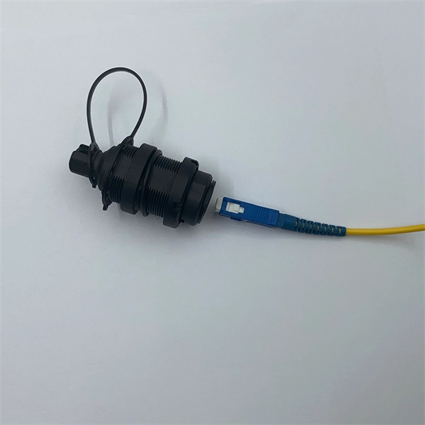
The fiber optic pigtail is a type of fiber optic cable with a pre-installed connector on one end while the other remains unterminated. This configuration allows the connector side to easily connect to equipment while the other end can be fused or mechanically spliced with other. Executive Summary: A fiber optic pigtail is one of the most commonly specified yet least understood components in structured cabling. Get the wrong connector type, the wrong polish, or skip proper fusion splicing technique—and you're looking at elevated signal loss, increased back reflection, and a. This is exactly why most professional installers have moved away from field-termination and toward splicing. The most efficient way to terminate a fiber run is by using a pigtail. more 🎥 Fiber Splicing Pigtails | Complete Step-by-Step Tutorial for Beginners and Technicians Welcome to our channel! In this detailed video, we'll walk you through the fiber optic pigtail splicing process — from preparation. Fiber optic joints or terminations are made two ways: 1) splices which create a permanent joint between the two fibers or 2) connectors that mate two fibers to create a temporary joint and/or connect the fiber to a piece of network gear. Either joining method must have three primary characteristics. The fiber optic pigtail is a short terminated optical fiber with a connector on one end, used to facilitate easy connections between fiber optic cables and various devices.
[PDF]

A novel method for aligning multi-core fibers (MCF) provides a systematic approach for MCF splicing in the lab, in cable factories, and in the field. Splicing fiber optic cable is an extremely important phase for making dependable, high-speed communication infrastructures. Regardless of the type of fiber network you're deploying, be it for telecom, enterprise data centers, or smart city infrastructure, fusion splicing provides the benefits of. This is where fiber optic cable splicing—the process of creating a permanent, high-performance join between two fiber ends—becomes critical. For network managers and technicians, a poor splice can lead to significant signal degradation, network downtime, and costly troubleshooting. At Turn-Key. W. Zheng, "Automated Alignment and Splicing for Multicore Fibers," in Optical Fiber Communication Conference/National Fiber Optic Engineers Conference 2013, OSA Technical Digest (online) (Optica Publishing Group, 2013), paper OM3I. However, realising its potential depends on one critical process, which is achieving ultra-low-loss fusion splices that maintain performance and. This guide reveals the secrets to fusion splicing with little fluff—just proven, straightforward techniques refined from years of work in the field. The guide provides the complete workflow, covering safety precautions, tool selection, fiber preparation, fusion operation, quality control, and.
[PDF]