An Optical Distribution Frame (ODF) is a dedicated unit designed to organize, terminate, and interconnect fiber optic cables. It brings together fiber splicing, patching, and cable routing in a single structure, while shielding sensitive connectors and splices from mechanical. In the complex architecture of fiber optic networks, the Optical Distribution Frame (ODF) serves as the linchpin for organizing, protecting, and distributing optical signals. Whether in data centers, telecom central offices, or enterprise network rooms, ODFs enable efficient fiber management. Among the many solutions available, the Optical Distribution Frame (ODF) plays a central role in organizing, protecting, and simplifying fiber management in telecom rooms, central offices, and data centers. As data centers, enterprises, telecom operators, and smart-building infrastructures deploy increasingly dense fiber links, ODFs provide the structured. Optical Distribution Frames (ODF) are indispensable components in optical communications networks. They provide efficient fiber optic management, connectivity, and protection. Whether you are building a data center, deploying FTTx networks, or managing the telecom systems, the selection of suitable ODF is very important since the fiber connections are optimized.
[PDF]
They are suitable for both single-mode and multimode fibers and are available in permanent or reenterable types. In contrast, fusion splicing offers a more robust solution by permanently welding the fiber ends together using an electric arc. The three basic fiber interconnection methods are: de-matable fiber-optic connectors, mechanical splices and fusion splices. De-matable connectors are used in applications where periodic mating and de-mating is required for maintenance, testing, repairs or reconfiguration of a system. The penalty. Auto Mode is the most intuitive and user-friendly splice mode. The fusion splicer automatically detects the fiber type, such as single-mode (SM), multimode (MM), or dispersion-shifted (DS) fibers, and adjusts parameters like arc power and heating time accordingly. Fusion splicing is the most widely used method of splicing as it provides for the lowest loss and least reflectance, as well as providing the strongest and most reliable joint between two fibers. Differences in ibers, equipment, environment. In this guide, you will find a chronological description of the fusion splicing process, the principal technical standards, and answers to the real-life questions network engineers and procurement teams may have. The guide provides the complete workflow, covering safety precautions, tool selection, fiber preparation, fusion operation, quality control, and.
[PDF]

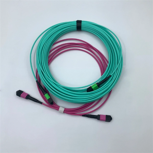
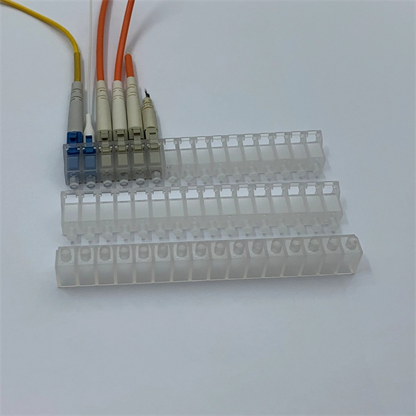
The LC Simplex to Blunt Single-mode (OS2) Splice-On Pigtail provides a dependable solution for terminating 900µm buffered fiber. This 2-meter assembly features a factory-terminated LC connector that is tested for low insertion loss and reliable performance. Leviton fiber optic pigtail kits are a good solution for mechanical or fusion splicing applications. Available in a range of multimode and single-mode fibers with SC, ST or LC connectors. Economy pigtails offer over a. Traditional Fusion Splice-On Connectors with pigtails provide factory-polished performance with field-termination convenience within harsh environments. Mass fusion splicing can fuse up to all 12 fibers in one ribbon at once. Closet Connector Housing (CCH) pigtailed splice cassettes enable faster field splicing and easy modular management of connectorization within the housing. They are preloaded and prerouted for quick fusion splicing of. Get it 12 May, 2026 108 in Global Warehouse. Get it 18 May, 2026 FS offers single mode & multimode fiber pigtails with tight buffer design for easy fusion or mechanical splicing. Quality assurance by 100% end-face, IL & RL testing. Each strand is terminated on one end and the other end is left blunt so that it can be spliced to your drop cable. Our fiber pigtails come with a partial outer jacket to help protect the tight buffer fibers.
[PDF]

Fusion splicing is the most widely used method of splicing as it provides for the lowest loss and least reflectance, as well as providing the strongest and most reliable joint between two fibers. Virtually all singlemode splices are fusion. There are two main methods of splicing: mechanical splicing and fusion splicing. This blog will delve into the nuances of each method, comparing their costs, labor efficiency, network performance, and more, to help you decide which splicing technique is best suited for your needs. Why splice? Fiber. Fusion splicing is the process of fusing or welding two fibers together usually by an electric arc. Fiber splicing means joining two optical fibers (permanently or temporarily) such that light guided in one fiber and reaching the joint (splice) can be transferred into the second fiber with low insertion loss. Another method of connecting optical fibers is termination or connectorization, which consists of processing the end of a fiber optic bundle so that it can be connected to other fibers or devices through fiber optic. Fiber Optic Cable is a form of modern network cable that has a far greater capacity than electrical communication connections. Splicing is typically required during cable installation, maintenance, or network expansion. The goal is to achieve the lowest possible optical loss (signal.
[PDF]

Towers are not rooted by only pouring concrete—they require extensive soil analysis, wind loads, types of towers, and seismic activity to determine the necessary foundation for safety and sustainable use. A communication tower foundation design is the structural blueprint that determines the anchor point of the tower on the ground. This article delves into the intricate process of civil construction tailored. Tower owners must comply with a multi-layered regulatory, engineering, and safety framework that governs tower siting, where a cell tower can be built, how it must be designed, and how it operates throughout its lifecycle. These requirements ensure public safety, structural integrity, regulatory. Here are six foundation types for communication towers that work for a wide range of situations and environments. If you're planning a new installation, knowing the basics of these foundations can help you establish a secure and durable tower that will be a community asset for years to come. Telecom (Telecommunications) towers are a generic description of radio masts and towers built primarily to hold telecommunications antennas. As such antennas often have a large area and must be precisely pointed out, such towers have to be designed and built to limit wind induced movement. The Contractor shall employ a quality control program that will ensure that engineering, fabrication.
[PDF]

It includes first determining the type of communication system (s) which will be carried over the network, the geographic layout (premises, campus, outside plant (OSP, etc. ), the transmission equipment required and the fiber network over which it will operate. Fiber optic network design refers to the specialized processes leading to a successful installation and operation of a fiber optic network. It also involves selecting transmission equipment. It includes detailed mapping of backbone, distribution, and drop connections for FTTH, FTTP, FTTx, and enterprise networks. Building a fiber optic network is a highly technical yet vital process that enables communities and businesses to access high-speed, reliable fiber optic internet. From the initial site survey to the final fiber to the home (FTTH) connection, every stage requires careful planning, coordination, and. Designing a fiber optic network is like planning a city's road system, it needs to be efficient, reliable, and built to handle both current and future traffic. Whether you're new.
[PDF]

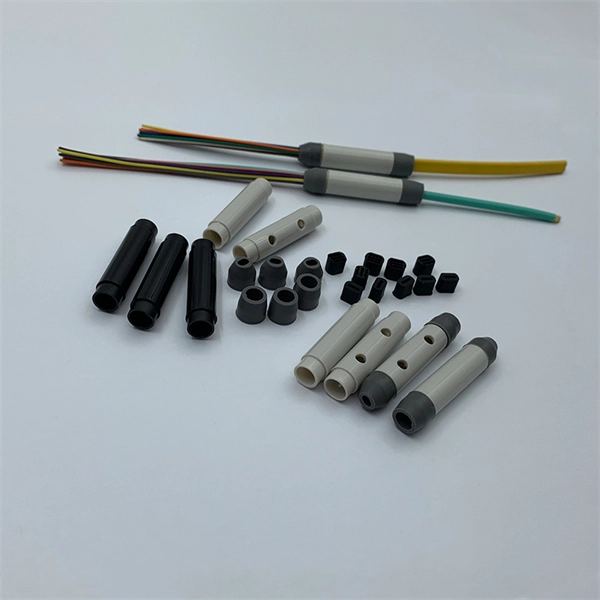
Given the access to a fusion splicer, you can splice the pigtail right onto the cable in a minute or less, which greatly speeds the splicing and saves significant time and cost spent on field termination. A fiber optic pigtail is a short length of optical fiber cable with a factory-terminated connector on one end and a bare, exposed fiber on the other. Unlike a patch cord—which has connectors on both ends—the bare fiber end of a pigtail is designed to be permanently spliced (either by fusion or. The Contractor tasked to perform testing or splicing on any fiber optic cable will follow these testing standards to fulfill their contractual obligations. The Contractor must utilize the correct equipment and testing techniques to gain acceptance, or the work cannot be approved. While for mechanical fiber optic pigtail splicing, it precisely holds a fiber optic pigtail. Fiber optic fusion splicing is on the rise and Corning's Pigtailed Splice Cassettes enable faster field splicing and easy modular management of connectorization within the housing. Pre-routed and preloaded, pigtailed splice cassettes reduce installation time by up to 40%. Today, fusion splicing. Next, we will introduce three common types: SC, FC, ST fiber optic pigtails. 5mm pre-radiused ferrule which is made of zirconia or stainless alloy.
[PDF]

This section explains that Article 250 focuses on general grounding and bonding electrical installation requirements, including: The grounding of systems, circuits, and equipment. Which circuit conductor must be grounded. Learn about the general requirements for grounding and bonding in line with the NEC 2023. The purpose of grounding is the safety of people and property. Grounding and bonding limit overvoltages, stabilize the voltage to the ground during regular functioning, and ease the proper operation of circuit. Electrical grounding is the process of connecting the non-current carrying parts of your home's electrical system—like metal boxes and appliance chassis—to the earth. In the event of a fault, such as a live wire touching a. Correct grounding of services depends upon understanding the definition and role of the grounded conductor. The neutral conductor is typically the grounded conductor connected to the system's neutral point, carrying current under normal operation. Grounding electrode conductors must be connected at. Properly grounding an electrical panel is one of the most critical safety measures in any home's electrical system. It is a non-negotiable requirement for protecting against severe electrical shocks, preventing electrical fires, and safeguarding sensitive electronics from power surges. The main goal of grounding is to limit voltages caused by lightning, line surges, or accidental contact with.
[PDF]
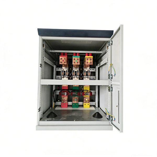
Choose the right box based on environment (indoor/outdoor), load capacity, and durability. Check for proper IP/NEMA ratings and material quality. Ensure safe placement: install in dry, accessible areas with good ventilation and at appropriate height (typically ~1. Practice good wiring: secure. Whether you are an electrical contractor or a construction brigade, knowing how to properly and safely install distribution boxes is the basis of ensuring the safe operation of the entire system. This article details the process of installing them, which helps you comprehend distribution boxes. Electrical systems power our homes, offices, and industrial facilities, but behind every reliable electrical setup lies a crucial component that often goes unnoticed: the distribution box. This essential piece of equipment serves as the nerve center of your electrical system, managing power flow. Everything you need about the wire and cable market, visualized. NEC Article 314 establishes requirements for the installation and use of electrical boxes, conduit bodies, fittings, and handhole enclosures. Whether it is residential buildings, commercial facilities or industrial sites, the. Publish Time: 03/08 2025 Author: Site Editor Visit: 918 The installation requirements and specifications of Distribution box involve many aspects, including site selection, fixing method, wiring specifications and safety protection. Site selection requirements: The distribution box should be.
[PDF]
3 specifies performance and transmission requirements for premises optical fiber cable, connectors, connecting hardware, and patch cords. Optical fiber transition methods used to connect cabling from an array connector to simplex or duplex connectors are also. ANSI/TIA-568-C. (FOA) was founded in 1995 to help develop the workforce to build the fiber optic networks to support a rapid expansion in communications and the Internet. The charter of the FOA was to promote professionalism in fiber optics through education, certification, and. ANSI/TIA‑568. 3‑E “Optical Fiber Cabling and Components Standard” was developed by the TIA TR‑42. 11 Optical Fiber Systems Subcommittee and published in September, 2022. A full catalog of TIA specs is at org/ Learning More About Standards and Codes There are a number of ways of finding out more about cabling. This specification covers the general requirements and characteristics for cables utilizing optical fibers for signal transmission. NOTE: The base document is not DLA Land and Maritime managed and is only here as a courtesy. Please use ASSIST Quick Search to ensure you have the latest version. This. This section covers Agency requirements for fiber optic service entrance cables intended for aerial installation either by attachment to a support strand or by an integrated self-supporting arrangement, for underground application by placement in a duct, or for buried installations by trenching.
[PDF]

The National Electrical Code (NEC) has established eight levels of fire resistance for fiber optic cables. These levels are based on the time it takes for a cable to burn through or melt. Corning Optical Communications manufactures quality flame retardant optical fiber cables for indoor applications, which comply with the requirements of the National Electric Code® (NEC® 2023) published by the National Fire Protection Agency (NFPA). To ensure compliance to these requirements, a. Understanding the listing requirements of fire alarm circuit cables can help you make sense of the cable alphabet soup. Here are some highlights from Part IV of Article 770. There's plenty of "expansion room" built into Article 770. Part I ends with Section 770. 44. Cabling Installation & Maintenance - Classes 1, 2, 3, and 4, communications, fire alarm, and optical fiber cables are all addressed in the NEC. By Stanley Kaufman, PhD, CableSafe Inc. UL Solutions' long-standing history in certification and Standards development makes us a trusted thought leader in the. Understanding the fire ratings and jacket options for fiber optic cables is crucial for ensuring optimal performance and safety. This technical guide will provide a comprehensive overview of these factors, their implications on cable resilience and transmission, and tips for making informed.
[PDF]
Distance relays, also known as impedance relay, differ in principle from other forms of protection in that their performance is not governed by the magnitude of the current or voltage in the protected circuit but rather on the ratio of these two quantities.OverviewIn, a protective relay is a device designed to trip a when a is detected. The first protective relays were electromagnetic devices, relying on coils operating on moving par. Electromechanical protective relays operate by either, or. Unlike switching type electromechanical with fixed and usually ill-defined operating voltage thresholds.
[PDF]
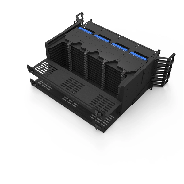
Mass fusion splicing can fuse up to all 12 fibers in one ribbon at once. Entire ribbons can be spliced simultaneously. Standard mass-fusion color-coded pigtail kits contain a. Traditional Fusion Splice-On Connectors with pigtails provide factory-polished performance with field-termination convenience within harsh environments. com offers Less-Than-A-Truckload “LTL” option for products that cannot be shipped via parcel shipping. For products that will be shipped via LTL, you will be provided with a set of Accessorials to select from to provide Anixter with additional shipping considerations, such as. The Relevance Inspector will open in the Coveo Administration Console. SDX Pigtail Fusion Metal Splice Module pre-loaded with duplex LC adapters (Blue) and 12-fiber OS2 LC/UPC individual pigtails. Works with all SDX Enclosures. SDX 12- and 24-fiber splice modules protect and organize heat shrink fusion spliced fibers (up to 12 or 24 fibers) inside a fiber enclosure. The modular design enables faster field splicing and simple management of pigtails within the housing. The M4 Splice Cassette is designed for use with Single-Mode OS2 fiber, houses 12 fibers, and provides LC UPC Duplex ports.
[PDF]
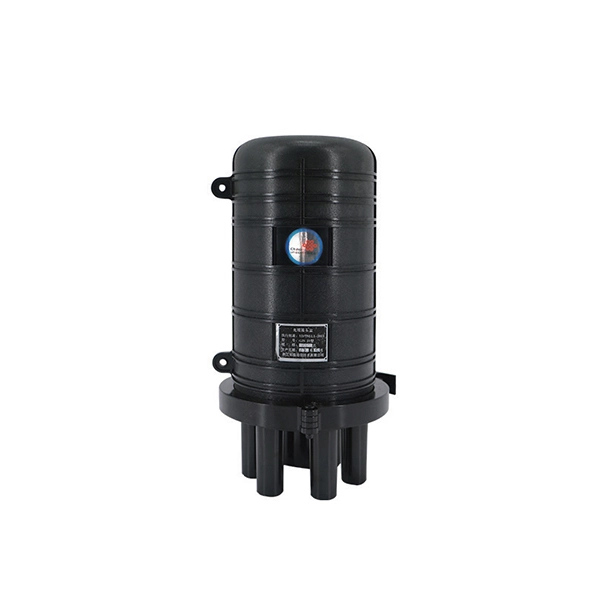
When deploying fiber optics in the field, telecommunications companies need ways to safely and efficiently store and terminate cables. As many technicians know, having the right fiber optic patch and splic.
[PDF]
In this guide, you will find a chronological description of the fusion splicing process, the principal technical standards, and answers to the real-life questions network engineers and procurement teams may have. What is Fiber Optic Splicing and Why is it Needed? – #1. Use and Maintain Your Cleaver Correctly – #3. Set Your Fusion Parameters in a Systematic Way What is Fiber Optic Splicing and Why is it Needed? First, let us understand the meaning of the term. Fiber optic splicing, crucial for maintaining seamless connectivity in modern communication networks, primarily uses two methods: fusion splicing and mechanical splicing. Therefore, we will also touch on cost factors, risk management, and best practices in. This is where fiber optic cable splicing—the process of creating a permanent, high-performance join between two fiber ends—becomes critical. For network managers and technicians, a poor splice can lead to significant signal degradation, network downtime, and costly troubleshooting. At Turn-Key. Fiber optic cable splicing connects two cables, creating a strong link for fast data transmission. Splicing fiber helps light signals move easily, ensuring your internet connection remains reliable. Another method of connecting optical fibers is termination or connectorization, which consists of processing the end of a fiber optic bundle so that it can be connected to other fibers or devices through fiber optic.
[PDF]