The socket accepts laser diodes with wire leads 24 to 26 gauge, 0. The maximum recommended current is 3 Amps. Specifications: Outside dimensions: 0. Thorlabs offers a versatile range of accessories for convenient integration of laser diodes into functional systems. These laser diode sockets are ideal for OEM-type implementations and are compatible with our selection of Ø3. 6 mm, Ø9 mm, and TO-5 laser diode packages. All of these sockets. Wide Range of Standard Products and Flexible Customization We offer a variety of standard products with different pitches, pin counts, and pin arrangements, helping to shorten lead times. Compatible with TO-18, TO-46, TO-52, TO-72, and more (please refer to the lineup at the bottom of the page for. Pricing (USD) Filter the results in the table by unit price based on your quantity. A tariff of 8% may be applied if shipping to the United States. A. Compact miniature socket size for maximum board density Accomodates most any TO package format with pin circle options of. The S8060 and S8060-4 sockets have a polarization dot on the top of. 4-Pins Laser Diode Test Socket High Precision Diode Test Stand 1. The inner hole of the pin is a through hole, and the length of the laser diode to be tested can be universal. The pins are made of gold-plated copper tubes, low resistance, not easy to oxidize, long service life.
[PDF]

This guide will walk you through the process of checking photo sensors using a multimeter, covering various types of photo sensors, the necessary tools and safety precautions, and the specific measurement techniques involved. Knowing how to effectively use a multimeter to test photo sensors can save you time, money, and frustration when dealing with malfunctioning devices. more What is a Voltage Divider? | What is a Voltage. Before replacing the sensor or fixture, it's efficient testing it first, With a few tools and a step-by-step process you can find whether your outdoor lighting control system is working as intended or if the problem lies elsewhere. In this complete guide from Lead-Top, a global leader in photocell. In this blog post, we explain step-by-step how to troubleshoot a sensor with a digital multimeter (DMM). Here are the steps: Troubleshooting a sensor measurement failure requires mechanical tools to uncover the protective shields or components so you can reach the sensor in question. Always follow the manufacturer's instructions for the sensor and multimeter. Ensure the sensor is properly connected to the multimeter and. A multimeter is an indispensable diagnostic tool for anyone working with electronics, electrical systems, or indeed, sensors. It's a versatile device capable of measuring voltage, current, and resistance, providing crucial insights into the health and functionality of electrical circuits and.
[PDF]

A wiring diagram for a photocell and timeclock controller provides a step-by-step guide for installing and connecting all the components in a light system. It shows exactly how each component fits into the overall scheme of things, as well as what wires to use and which connections to. Intelligent Lighting Controls' wiring diagrams show detailed schematics of our solutions. A lighting control module is the “control center” for your lighting system. It acts as a bridge between your physical lighting fixtures and the smart systems that manage them. Instead of relying solely on traditional wall switches, you can control your lights via remotes, mobile or web apps. This guide will discuss the steps needed to integrate with URC Total Control. Commission CSI Controllers Step 2. Locate/Download latest TCM files/Module Step 3. Network Setup Step 6. Supports DALI V2 compatible switches and sensors, works out of the box. Simple and easy setup. ControlByWeb® IoT controllers are a great fit for lighting control in edge applications. Understanding the components that make up a modern lighting system, and how they relate to one another is key to ensuring the best performance and.
[PDF]
This guide provides step-by-step instructions for connecting a distribution box and highlights key factors to consider during installation. What Is a Distribution Box? A distribution box, also known as an electrical distribution board, is a critical component. In this guide, we will break down the key elements involved in connecting the main power supply to your home, providing a clear path for a successful setup. We will focus on the critical parts of the system, from basic components to step-by-step assembly procedures. Whether you are looking to. In this guide, we'll break down everything you need to know to install a distribution box correctly and confidently. Choose the right box based on environment (indoor/outdoor), load capacity, and durability. Check for proper IP/NEMA ratings and material quality. Ensure safe placement: install in. A distribution board or distribution box is where the main power supply is distributed to multiple loads. And all the switching and protective devices are installed in the distribution box. Single Phase Distribution Box generally consists of Double Pole MCBs, Single Pole MCBs, and RCCBs. The Main feeder cable to the Distribution Board should be able to handle the total power anticipated when all the sub circuits in the Distribution Board. Welcome to our channel! In this video, we'll walk you through the process of wiring a home distribution box with a detailed connection diagram. more Welcome to our.
[PDF]

Average Optical Power: How bright the light is (measured in dBm). Too dim? Your signal gets lost in the fiber. Extinction Ratio: The difference between “on” (1) and “off” (0) light power. A higher ratio = cleaner signals. Transmitter Side: An electrical signal hits a laser diode (LD) or LED, which spits out light. Receiver Side: Light enters a photodetector (like a tiny solar cell), which turns it back into electricity. A built-in amplifier boosts the signal for your. The average transmitted optical power refers to the optical power output by the light source at the transmitting end of the optical module under normal working conditions, which can be understood as the intensity of light. In communication, we usually use dBm to represent optical power. However, in practical use, we adopt the average Tx power. The transmission power is related to the. This article provides an in-depth analysis of two key performance indicators of optical modules: transmitter power and receiver sensitivity. Transmitter power characterizes the average optical power output from the laser under rated conditions, while receiver sensitivity indicates the minimum. An optical module is a connecting module that serves as an optical-electrical conversion device. At the receiver end, the optical signals are reconverted into electrical.
[PDF]

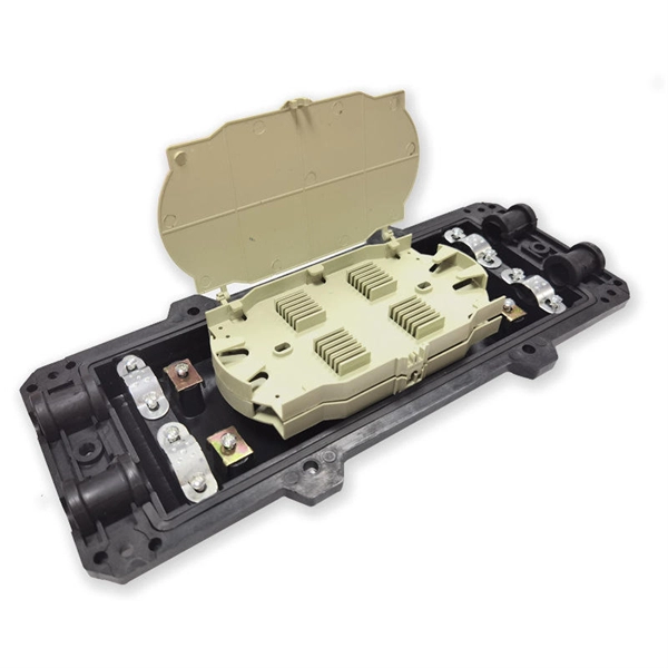
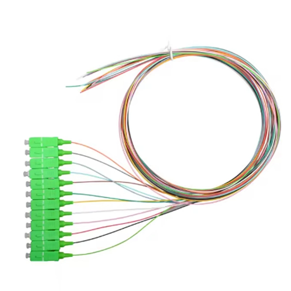
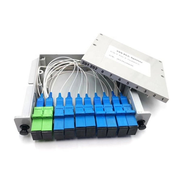
A fiber-optic splitter, also known as a beam splitter, is based on a quartz substrate of an integrated waveguide optical power distribution device, similar to a coaxial cable transmission system. The optical network system uses an optical signal coupled to the branch distribution. The fiber optic. In the backbone of modern Fiber-to-the-Home (FTTH) networks, optical splitters serve as the unsung heroes that enable cost-efficient connectivity for millions of subscribers. By dividing a single optical signal from a central Optical Line Terminal (OLT) into multiple outputs for Optical Network. Optical splitter, also called optical beam splitter, is an integrated waveguide optical power distribution device that can split an input optical signal into two or more output optical signals, and the optical input power is evenly distributed on all output ports. For example, an optical splitter. The answer lies in a small device. We call it an Optical Splitter. This device is the heart of Passive Optical Networks (PON). It allows service providers to save money. It helps them distribute bandwidth efficiently. In this article, we explain the definition, working principles, types, and. An optical splitter is a device that divides light transmission in a network into multiple output ends. It plays a crucial role in facilitating network interconnections.
[PDF]

Fiber optic connector pull test demonstration with real-time insertion loss monitoring. We use an optical loss tester to track signal stability every second while controlled tension is applied to the fiber. more. Fiber optic cable is surprisingly strong, durable and pliable; however, several best practices should be followed to ensure a successful cable installation. The below article explores the best practices and tools commonly used to pull fiber optic cable. The Future Ready Solutions Tools & Test. NEOFIBO TFTM-100N Vertical Fiber Optics Cable Tension Testing Machine The Cable Tensile Testing Machine is a precision mechanical measuring instrument designed to evaluate the tensile strength and elongation properties of various cables, wires, and fiber optic assemblies. Most fiber damage does not come from normal operation after the system is live. It happens during installation, when excessive pulling force, tight bends. Fiber optic connectors are designed to be connected and disconnected many times without affecting the optical performance of the fiber circuit. Optimal performance can be achieved by following the correct process for termination of the fiber circuit—a task which requires the use of a wide range of. The Fluke Networks JR-LEV-1 JackRapid Punch Down Tool is a cable termination tool that is designed to give technicians maximal efficiency in cable maintenance.
[PDF]

The fastest way to test a fluorescent tube is with a multimeter set to continuity mode. Each end of the tube has two pins connected by a thin filament inside the glass. If either filament is broken, the tube is dead. The whole test takes about 30 seconds per tube once you know what. This is a complete guide for testing a fluorescent light bulb with a multimeter. You don't have to be an expert in electrical work. This process measures electrical resistance to determine if the tube has suffered an internal failure before replacing the bulb or investigating the ballast. This guide provides a comprehensive understanding of the process, equipping you with the knowledge and. To test a fluorescent light bulb, observe any of the following: flickering light, low brightness, buzzing sound, delayed start, and fading color and light variation. Turn off the power to the circuit that powers the fixture and keep the leads steady to ensure accurate readings. Multimeters provide. How to Test Light Bulbs & Fluorescent Tubes with a Multimeter (Continuity Check) Is your lamp or fixture failing to light up? Before you buy a new bulb, you need to confirm if the bulb or tube itself is the problem! A simple continuity check using a multimeter can instantly tell you if the filament.
[PDF]

The PV combiner box test in solar power systems is a fundamental procedure that verifies the accuracy of string connections and the electrical current flowing to inverters. This test helps prevent energy losses while optimizing system performance. ance cables by combining strings at the array locat ciency, reliability and safety in solar energy systems. They enable centralized management in large-scale and remote installation ity), equipment aging, and poor installation practices. MapperX performs this critical test professionally. This guide provides a step-by-step method for safely testing energized PV strings to locate intermittent ground faults using reliable tools and procedures. What Is an Intermittent Ground Fault? An intermittent ground fault is a temporary electrical connection between a current-carrying conductor. A PV combiner box, often referred to as a solar combiner box, is a critical component in solar energy systems. This device plays a significant role in both residential and commercial solar installations, particularly when. We do a lot of solar PV and renewable energy asset inspections here at HelioVolta and SolarGrade! Every time we visit a site, we use the SolarGrade platform to guide our workflow and document our findings. Missing/Improper Label Improper labeling can be a risk to personnel and should conform to.
[PDF]
A solar meter, also known as a solar irradiance meter or pyranometer, is a device that measures the amount of solar energy or irradiance emitted by the sun. It is commonly used in solar power applications to op.
[PDF]
More than $69million (USD$30. 51m) will be channeled to Fiji in highly concessional capital via the multinational development partner-funded Climate Investment Fund (CIF) – to transform systems and enable the electricity grid to absorb and channel more clean power. The CIF governing board has. This International Merchandise Trade Statistics provides information on Fiji's exports, re-exports and imports of goods between Fiji and the rest of the world. The administrative data used to compile this release is supplied by the Fiji Revenue and Customs Service (FRCS). The REI Plan which represents a first-of-its-kind effort that will channel.
[PDF]
Energy consumption growth of the fifth-generation (5G) mobile network infrastructure can be significant due to the increased traffic demand for a massive number of end-users with increasing traffic volum.
[PDF]
When encoding diffractive optical elements (DOE) onto a spatial light modulator (SLM), the diffraction efficiency can be reduced because of the pixel nature of the SLM. These effects have been studied previousl.
[PDF]
Solid Green: The ONT is powered on and functioning normally. What to check: Make sure the power cable is securely plugged into both the ONT and a working wall outlet. If you're using a power strip, check that it's turned on. Learn what each light on your fiber equipment means—from power and fiber signal to Ethernet and phone service—and how to quickly troubleshoot issues. This light shows whether your ONT is getting power. No Light: The ONT is not receiving. The Optical Network Terminal (ONT) is a crucial device in modern telecommunications, serving as the interface between your home network and the fiber-optic internet connection provided by your Internet Service Provider (ISP). The ONT has a series of lights that indicate its status and any potential issues. In this article, we will delve into. Power down for 15mins then power back on and wait 3mins for the lights to settle Power connector has come loose. Problem with the plug socket. Optical: This should be a solid green at all times (If the power light is off, this will also. This guide is designed to offer an explanation on how to troubleshoot issues with a CityFibre ONT (Optical Network Terminal). For more help topics, please visit the main Support Page. If you would like details on Freeola Broadband tariffs using the CityFibre Network, please visit our Broadband. You can use the status lights on your optical network terminal (ONT) to help find and fix internet issues. An ONT may also be called a Service box.
[PDF]
A beam splitter or beamsplitter is an optical device that splits a beam of light into a transmitted and a reflected beam. It is a crucial part of many optical experimental and measurement systems, such as interferometers, also finding widespread application in fibre optic telecommunications. DesignsIn its most common form, a cube, a beam splitter is made from two triangular glass which are glued together at their base using polyester,, or urethane-based adhesives. (Before these synthetic,. Beam splitters are sometimes used to recombine beams of light, as in a. In this case there are two incoming beams, and potentially two outgoing beams. But the amplitudes. For beam splitters with two incoming beams, using a classical, lossless beam splitter with Ea and Eb each incident at one of the inputs, the two output fields Ec and Ed are linearly related to the inputs thro.
[PDF]