This guide dives deep into the most prevalent fiber optic network problems, their root causes, and actionable solutions. Fiber optic technology is essential for modern communication, offering unparalleled speed, reliability, and efficiency. However, improper installation can lead to severe performance issues, expensive repairs, and unnecessary downtime. To ensure a high-functioning fiber optic network, avoid these. Understanding the common causes of failure and implementing preventive measures is essential to maintaining reliable networks and avoiding costly downtime. In this article, we explore the primary modes of field failure in fiber optic cables and outline best practices to prevent them. This article outlines three key errors and how to avoid them.
[PDF]

This is the most fundamental ring topology, formed by connecting three or more switches in a closed loop using fiber optic cables. Data can flow in either direction, allowing the network to recover quickly if a link fails. If you have multiple Ethernet switches that need to be connected over long distances, fiber is obviously a preferred choice. Moreover, when it comes to bandwidth, no currently available technology is better than single-mode fiber. It can provide significantly higher bandwidth and carry more data. A single 6 strand fiber can only connect 3 switches back to the core. How many switches do you plan to connect? A star is great for a limited number of switches. I have maybe 20 coming back to my cores. Rings are generally not done anymore, but I think that is for bandwidth as much as anything else. The mainline of the fiber optic LAN directly connects to the switch, then to the router. The connection between two or more Ethernet switches in a certain way (Uplink port, etc. ) is called the cascade. All switches have two fiber ports. Is the best way to have fiber backbone switch and connect fiber channel from every switch to the backbone? Or connect switch 1 to switch 2 to switch 3 to. switch 12 to switch 1 again? Thanks! Let's get some. I need to connect 4 Floor Building with 4 Cisco 2960 - 48 ports switch each other and it needs to be through a fiber. This design ensures data can travel in both directions.
[PDF]
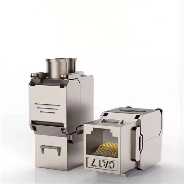
The short answer is no - RJ45 connectors are designed for electrical Ethernet signals, while fiber optics transmit light pulses through glass or plastic. However, modern networks often combine both technologies. Fiber optic internet is a high-speed, reliable solution for modern connectivity, offering superior performance for both residential and enterprise networks. Fiber optic technology is a method of transmitting information from one point to another using light signals that are transmitted along thin, flexible fibers made of glass or plastic. It has become an essential component of our daily lives, providing fast and reliable communication over long. This tutorial explains the types of network cables used in computer networks in detail. Learn the specifications, standards, and features of the coaxial cable, twisted-pair cable, and fiber-optical cable. To connect two or more computers or networking devices in a network, network cables are used. Network cable connectors have various types and work for certain purposes. This article is a complete guide. It will give you an overview of these types and describe how they work. The fundamental difference between optical fiber and Ethernet cables is that optical fiber cables transmit data using light signals, while Ethernet cables transmit data using.
[PDF]
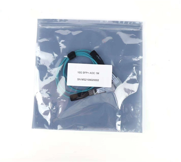
The Fibre Channel physical layer is based on serial connections that use fiber optics to copper between corresponding pluggable modules. The modules may have a single lane, dual lanes or quad lanes that correspond to the SFP, SFP-DD and QSFP form factors. Fibre Channel does not use 8- or 16-lane modules (like CFP8, QSFP-DD, or COBO used in 400GbE) and there are no plans to use these expensive and comple.
[PDF]
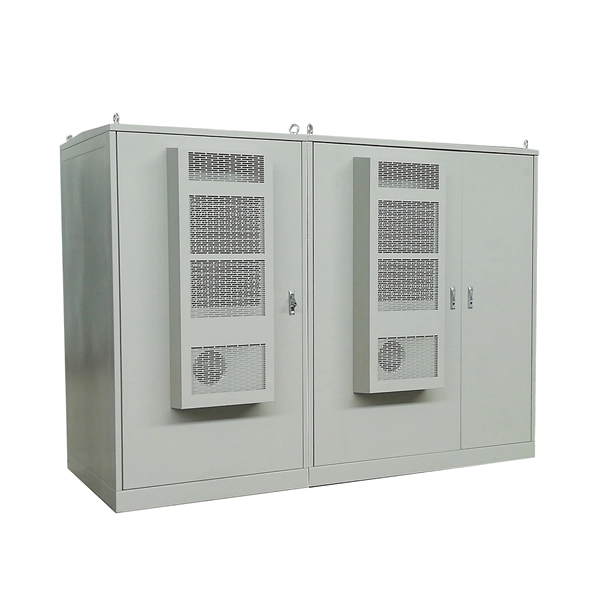
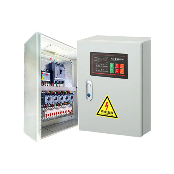
Manufacturers design fiber optic cabinets to protect fiber optic cables in indoor and outdoor environments. Also known as fiber optic enclosures or fiber entrance cabinets, these enclosures act as hubs where ca.
[PDF]
A passive optical network (PON) is a fiber-optic telecommunications network that uses only unpowered devices to carry signals, as opposed to electronic equipment. In practice, PONs are typically used for the last mile between Internet service providers (ISP) and their customers. In this use, a PON has a point-to-multipoint topology in which an ISP uses a single device to serve many end-us. Components and characteristicsA passive optical network consists of an (OLT) at the service provider's central office (hub), passive (non-power-consuming) optical splitters, and a number of (ONUs) or. Passive optical networks were first proposed by in 1987. Two major standard groups, the (IEEE) and the. A PON takes advantage of (WDM), using one wavelength for downstream traffic and another for upstream traffic on a (ITU-T, typically OS2). BPON, EP.
[PDF]

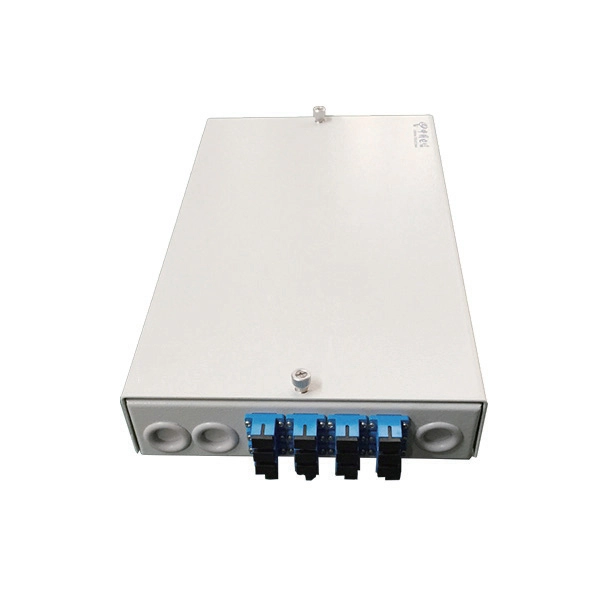
A fiber patch panel is a mounted enclosure—either rack-mounted or wall-mounted—used to terminate, manage, and interconnect multiple fiber optic cables. It acts as a hub for organizing splices and patch cords, streamlining fiber management and preserving signal integrity. Cable Organization:. Structured cabling is a standardized system to help you organize and install the cables and hardware that connect your different devices to your network (including computers, servers, cameras, or any other smart gadgets). Structured cabling uses consistent components, such as patch panels, jacks. A fiber distribution panel is also called a fiber patch panel. It helps you keep fiber optic cables neat in your network. You use this device to connect and separate fiber cables. It does not need power to work. Serving as the network's centralized junction, it provides secure ports for both incoming and outgoing. Fiber optical patch panels can help data center management cables. Do you know which types are available? What are their functions? This article will show you. With the development of data centers, the cabling infrastructure is getting larger and larger, the patch panel gives the data center a. A patch panel, including fiber patch panels and Ethernet patch panels, is a passive network device that centralizes, terminates, and organizes multiple copper or fiber cables.
[PDF]
Locate your ONT/ONU: This is typically a small box provided by your ISP, often located near where the fiber optic cable enters your home. Connect the fiber optic cable: Plug the fiber optic cable from your ISP into the designated port on your ONT/ONU. This is usually clearly labeled. However, setting up a fiber optic connection to your router can seem daunting if you're unfamiliar with the process. In this guide, we'll walk you through how to connect a fiber optic cable to a router safely and efficiently. Why Use Fiber Optic Internet? Before diving into the setup, let's quickly. To set up your router for fiber internet quickly, connect the router to your fiber modem, access the router's settings via a web browser, and input the provided ISP credentials. Make sure to update the firmware, configure Wi-Fi security, and customize your network name for optimal performance. With. Setting up a fiber internet connection requires understanding key hardware components and following a specific connection sequence to establish your home network. Here's a simple guide to help you through the process: 1. Check Your Fiber Optic Equipment Before you start, make sure you have the necessary equipment: Fiber Optic Modem (ONT – Optical Network Terminal):.
[PDF]
In this comprehensive guide, we'll walk through the best practices for installing various types of fiber optic cable, from patch cords to distribution fiber, and provide practical tips to ensure a successful installation. The processes. Fiber optic installation delivers unmatched network performance for modern businesses, providing greater bandwidth capacity and superior resistance to electromagnetic interference compared to traditional copper cables. Professional installation ensures optimal performance and higher reliability for. In the spirit of self-reliance and technical mastery, we've crafted this detailed guide to empower you to take control of your own network by installing fiber optic cables yourself. In this guide, we will walk you through a step-by-step process for the installation of fiber optic cables. The number one cause of signal loss in optical fiber installations is dirt on. In this comprehensive guide, we'll cover everything you need to know about fiber optic cabling—from key components and installation procedures to best practices for network design and maintenance. What is Fiber Optic Cabling? Fiber optic cables transmit data as pulses of light through strands of.
[PDF]
The Gateway Cities Council of Governments' (GCCOG) Gateway Cities Fiber Optic Network Project will expand fiber optic infrastructure, aiming to establish a new regional fiber network to address the digital divide and provide high-speed internet access. The FOA created its Online Reference Guide to provide a more up-to-date and unbiased reference for those seeking information on cabling and fiber optic technology, components, applications and installation. It's success confirms the assumption that many users prefer the Internet for technical. Building a fiber optic network is a highly technical yet vital process that enables communities and businesses to access high-speed, reliable fiber optic internet. From the initial site survey to the final fiber to the home (FTTH) connection, every stage requires careful planning, coordination, and. Fiber optic network design is not simply a theoretical framework—it is a disciplined engineering process that determines how infrastructure will perform, scale, and be maintained over the next 20 to 30 years. The project involves building significant.
[PDF]
Mouser offers inventory, pricing, & datasheets for Fiber Optic Sensors. Pricing (USD) Filter the results in the table by unit price based on your quantity. A tariff of 8% may be applied if shipping to the United States. Check each product page for other buying options. Need help?. Explore 71 top manufacturers and suppliers of Fiber Optic Sensors in our comprehensive photonics buyers' guide. A fiber optic sensor is a device that uses optical fibers to detect and measure physical, chemical, biological, or environmental parameters. Unlike traditional electrical sensors, fiber. Fiber optic temperature sensors have revolutionized temperature monitoring across critical industrial applications with their exceptional accuracy, EMI immunity, and reliability in extreme environments. For decision-makers evaluating these advanced monitoring solutions, understanding the pricing. Call one of our engineers at 1-802-880-3123. Infrared or visible red light fiber-optic amplifier for tight installation spaces. Can be used as a through-beam or proximity sensor depending on fiber cables used. Up to 20m max sensing. Starting at USD 2. 37 Billion in 2026, the global Fiber Optic Sensors Market is set to witness notable growth. By 2035, it is projected to reach USD 6. 3% throughout the forecast period from 2026 to 2035. I need the full data tables.
[PDF]
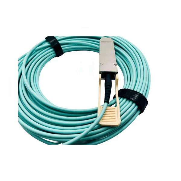
Fiber optic connectors can be categorized according to different standards such as utilization, fiber count, fiber mode, and transmission method. They are also divided into single-mode and multimode types based on their distinct characteristics. This guide will walk you through the most common fiber connector types, explaining their characteristics, advantages, and typical use cases. Whether you're planning an FTTH deployment, upgrading a data center, or working in telecom infrastructure, this guide will help you make informed decisions. Compared to Copper cables, Fiber connector types are incredibly varied. Where copper twisted pairs tend to terminate with an RJ45 plug, fiber optic connectors come in all sorts of shapes and sizes, with all manner of different use cases in mind. An optical fiber connector is used to join optical. With a wide variety of connector types available, choosing the right connector for your network can be challenging. Learn how each connector works, where it's used, and how to choose the right option for today's high-density, high-speed networks. It is a precise coupling device that joins fiber optic cables quickly, enabling faster connection and disconnection than splicing. The connector mechanically orients the fiber cores, allowing light to pass and travel through. In this guide, you'll explore various types of fiber optic cable connectors, each with unique features and best uses. We'll also provide practical advice.
[PDF]

An undersea fiber-optic cable between mainland Norway and the archipelago of Svalbard in the Arctic Ocean has been lost in a mysterious event. The outage of the submarine telecommunications cable - the northernmost submarine telecommunications cable in the world - follows an accident last year. The. The archipelago still has communication, but no redundancy. Photo: Thomas Nilsen There is no redundant between the Arctic archipelago and mainland Norway after loss of power in the area where the fiberoptic cable follows the seabed down to a depth of 2,700. A diver works on an underwater cable off the coast of Papua New Guinea. Believe it or not, Svalbard, Norway has famously reliable internet — and has since 2003. The remote arctic archipelago sits almost 2,000km away from the mainland, at about 80˚N, but its nearly 3,000 residents have surfed the. LILLESTRØM, Norway — Undersea cables have been transmitting communications since the 1850s, but the now ubiquitous technology is grabbing headlines as NATO nations accuse bad actors of sabotaging fiber-optic lines in the Baltic Sea. Attacks on undersea infrastructure came to the fore in September.
[PDF]

A typical fiber optic splice enclosure consists of several key components that work together to protect and organize the fiber splices. Standard enclosures contain: 1) Housing, 2) Cable fixation clamps, 3) Splice trays, 4) Sealing system. A splice box (also known as splice distributor) is a housing in which fiber optic cables begin or end. Fiber optics are fanned out in splice boxes that are situated at the end of fiber optic transmission paths. Optical cable joint box The optical cable joint box permanently connects two optical cables together and has a joint part for protecting components. The optical cable connection part, that is, the optical cable joint, is the part where the. An optical cable split fiber box, also known as a fiber distribution box or fiber optic splice closure, is a device used to terminate, splice, and distribute optical fibers. In this response, we will focus on the. This guide optimizes the original text by delving deeper into the three pillars of fiber network longevity: the impact of splicing technology, the strategic selection of splice boxes, and the essential maintenance protocols needed to ensure sustained, high-speed functionality. Fibre optic cables are manufactured in standardized lengths –.
[PDF]

While optical power meters are the primary power measurement instrument, optical loss test sets (OLTSs) and optical time domain reflectometers (OTDRs) also measure power in testing loss. TIA standard test FOTP-95 covers the measurement of optical power. This measurement is the basis for loss measurements as well as the power from a source or presented at a receiver. Typically both transmitters and receivers have receptacles for fiber optic connectors, so measuring the. You need a power meter to measure power in a fiber optic system; most power meters come with a screw-on-adapter that matches the connector being tested and a little aid from the network electronics to turn on the transmitter. During the measurement of power, the meter must be set to the proper. Fluke Networks sets the standard in network testing with its advanced range of fiber optic power meters and fault locators, designed to ensure the highest precision in fiber optic meter readings and power evaluations. This is measured in decibels (dB). Splitters, fusion splices, connectors and. To use a power meter for fiber optic testing, always clean connectors first with lint-free wipes or click-to-clean tools. Select the correct wavelength and set your reference. Consistent procedures ensure accuracy.
[PDF]