
The OPM 510 and 520 are available in standard and high-power versions for the Telco and MSO markets. The OPM510 and OPM520 supports wavelengths of 850, 980, 1270 1300, 1310, 1490, 1550, 1577, 1623 and 1650nm. The rugged enclosure provides confidence when testing singlemode and. Count on Tempo Communications Optical Power Meters (OPM510/520) to test and maintain your fiber optic networks. Our optical power meters feature built-in calibration factors. Optical power meters and detectors have been served by Newport for over 30 years. The offering ranges from a low cost, hand-held meter to the most advanced dual channel benchtop power meter available in the market. Our 1936-R/2936-R series boasts state-of-the-art analog boards with a whopping 250. © Copyright© Santec Holdings Corporation. Demo the full range, from multi-use to dedicated PON and FTTH. VIAVI offers fast, cost-effective, and easy-to-use power meters for installation and maintenance of single mode and multimode fiber optic networks and. AFL is a trusted supplier of optical testing equipment with more than 30 years of experience and tens of thousands of units in use in the field. AFL's full range of power meters are used for testing single-mode and/or multimode fiber networks. Power meters with wave ID can detect two or more.
[PDF]

An Optical Splitter, also known as a beam splitter, is a passive optical device that divides a single input optical signal into two or more output signals. Conversely, it can also combine multiple signals into one. Knowing the difference between a splitter and an optical coupler helps you build better networks. You make your network work better when you pick the right device for each job. You can connect many users to one port with 1:n or 2:n splitters. By dividing a single optical signal from a central Optical Line Terminal (OLT) into multiple outputs for Optical Network Terminals (ONTs) at users' homes, splitters eliminate the need for dedicated fibers to each residence—slashing infrastructure costs while scaling network reach. This guide. In a Passive Optical Network (PON), a single optical fiber carries massive amounts of data using light. Signal Input: The fiber splitter receives the optical signal from the upstream network node and enters the splitter through the input fiber. Signal Distribution: Inside the splitter, according to the design structure and different. Splitters are passive optical devices that divide or combine optical signals, and they come in various types, including power splitters, uneven splitters, and wavelength-division multiplexing (WDM) splitters. Each type serves specific applications, enabling efficient use of optical infrastructure.
[PDF]
Choose the right box based on environment (indoor/outdoor), load capacity, and durability. Check for proper IP/NEMA ratings and material quality. Ensure safe placement: install in dry, accessible areas with good ventilation and at appropriate height (typically ~1. The National Electrical Code (NEC) provides comprehensive safety standards for electrical installations, including requirements for electrical panels (main service panels and subpanels or breaker box). NEC Article 408 covers switchboards, switchgear, and Panelboards installation and applications. In this guide, we'll break down everything you need to know to install a distribution box correctly and confidently. Just like travelers need clear pathways and safety protocols, your electrical circuits need proper management to prevent chaos. 26 requires electrical equipment (including electrical panels) to be located to provide required working clearances about the equipment. You can find electric panels inside cabinets, behind refrigerators, or inside clothes closets in older homes. Current National Electrical Codes (NEC) allow none of these locations. Expect to pay $1,500 to $2,000 to move an electrical panel, with replacement adding another $1,150 if your existing box needs upgrading.
[PDF]

The International Protection (IP) rating system defines minimum requirements for water and dust ingress protection, with outdoor applications typically requiring IP65 or higher ratings. Weatherproof outdoor distribution boxes ensure reliable power distribution in challenging environments by protecting against moisture, dust, and temperature extremes. Key design points include high-quality materials like ABS plastic, aluminum, and stainless steel that resist corrosion and UV. (1) Waterproof distribution box engineered for harsh outdoor and industrial environments, providing IP65–IP68 sealing against dust, rain, and UV. Beyond preventing acute water damage, these enclosures also protect against humidity-related. Yet one factor often overlooked is how well electrical components are protected from dust and moisture. That's where Ingress Protection (IP) ratings come in. If you've ever bought a weatherproof junction box or a distribution enclosure, you've probably noticed codes like IP65, IP67, or IP68 printed. Low voltage distribution box outdoor use requires IP65 or NEMA 4X ratings, corrosion-resistant materials, and proper sealing for lasting weather protection. You use a low voltage distribution box to keep electrical systems safe outside. Let's take a closer look at NEMA ratings and other weatherproofing considerations for.
[PDF]

The National Electrical Code (NEC) has established eight levels of fire resistance for fiber optic cables. These levels are based on the time it takes for a cable to burn through or melt. Corning Optical Communications manufactures quality flame retardant optical fiber cables for indoor applications, which comply with the requirements of the National Electric Code® (NEC® 2023) published by the National Fire Protection Agency (NFPA). To ensure compliance to these requirements, a. Understanding the listing requirements of fire alarm circuit cables can help you make sense of the cable alphabet soup. Here are some highlights from Part IV of Article 770. There's plenty of "expansion room" built into Article 770. Part I ends with Section 770. 44. Cabling Installation & Maintenance - Classes 1, 2, 3, and 4, communications, fire alarm, and optical fiber cables are all addressed in the NEC. By Stanley Kaufman, PhD, CableSafe Inc. UL Solutions' long-standing history in certification and Standards development makes us a trusted thought leader in the. Understanding the fire ratings and jacket options for fiber optic cables is crucial for ensuring optimal performance and safety. This technical guide will provide a comprehensive overview of these factors, their implications on cable resilience and transmission, and tips for making informed.
[PDF]
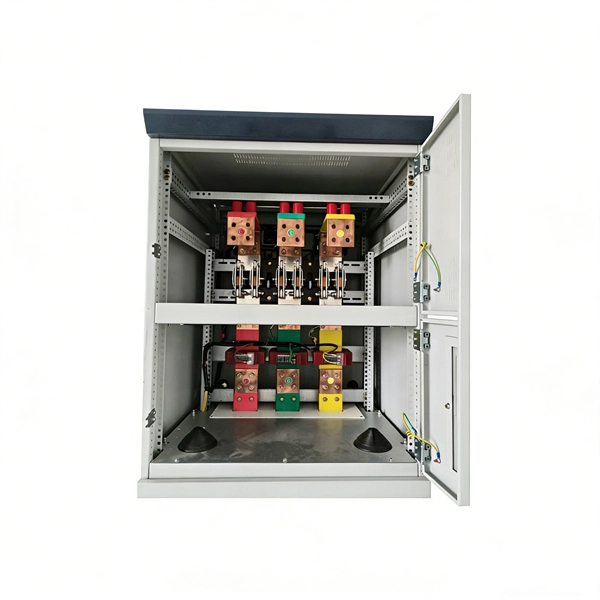
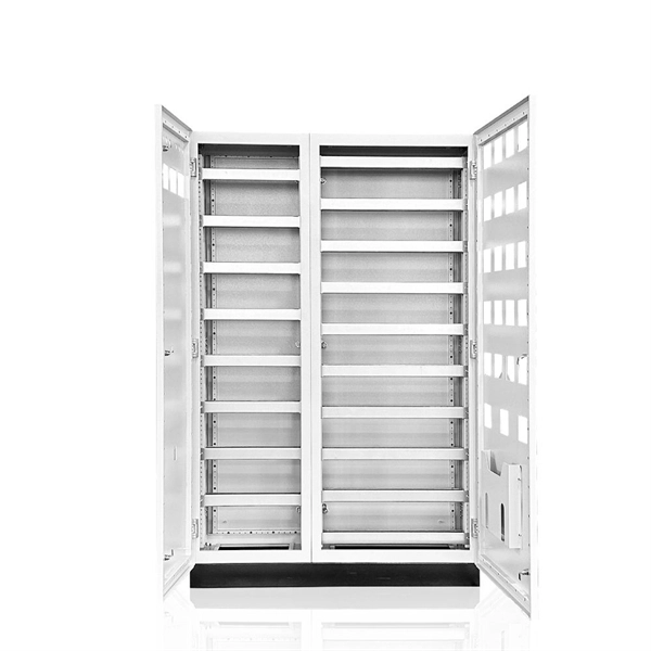
Choose the right box based on environment (indoor/outdoor), load capacity, and durability. Check for proper IP/NEMA ratings and material quality. Ensure safe placement: install in dry, accessible areas with good ventilation and at appropriate height (typically ~1. Practice good wiring: secure. Whether you are an electrical contractor or a construction brigade, knowing how to properly and safely install distribution boxes is the basis of ensuring the safe operation of the entire system. This article details the process of installing them, which helps you comprehend distribution boxes. Electrical systems power our homes, offices, and industrial facilities, but behind every reliable electrical setup lies a crucial component that often goes unnoticed: the distribution box. This essential piece of equipment serves as the nerve center of your electrical system, managing power flow. Everything you need about the wire and cable market, visualized. NEC Article 314 establishes requirements for the installation and use of electrical boxes, conduit bodies, fittings, and handhole enclosures. Whether it is residential buildings, commercial facilities or industrial sites, the. Publish Time: 03/08 2025 Author: Site Editor Visit: 918 The installation requirements and specifications of Distribution box involve many aspects, including site selection, fixing method, wiring specifications and safety protection. Site selection requirements: The distribution box should be.
[PDF]
Energy Internet integrates small-scale renewable energy systems, electric loads, storage devices, and electric vehicles for effective transaction of power backed by emerging technologies such as Internet of Things, vehicle-to-grid, and blockchain. Energy Internet, a futuristic evolution of electricity system, is conceptualized as an energy sharing network. Its features, such as plug-and-play mechanism, real-time bidirectional flow of energy, information, and money can lead to significant benefits and innovation in electricity production and. This textbook is the first of its kind to comprehensively describe the energy Internet, a vast network that efficiently supplies electricity to anyone anywhere and is an internet based wide area network for information and energy fusion. The chapters are organized into five parts: Architecture and. This work was supported in part by the Academy of Finland EE-IoT Project under Grant 319009, in part by the FIREMAN Consortium CHIST-ERA under Grant 326270, and in part by the EnergyNet Research Fellowship under Grant 321265 and Grant 328869.
[PDF]
The American Society of Civil Engineers Standard 7: Minimum Design Loads and Associated Criteria for Buildings and Other Structures (ASCE 7), Chapter 13 defines seismic design requirements for the bracing of distribution systems. mplied exemptions that are stated as requirements. This section will attempt to more fully define these provisions for the design professional responsible for the design of the electrical components and distribution systems, and also for the installing contractor who is res onsible for bidding and. Functional Requirements. Nonstructural Component. Normal Operating. Eaton's electrical distribution and control equipment has been tested and seismically proven against requirements defined within the International Building Code (IBC) and the California Building Code (CBC). This IR is applicable to all projects under DSA. Seismic loads for electrical raceways, conduit, cable trays, and bus ducts are determined using ASCE/SEI 7-10, Minimum Design Loads for Buildings and Other Structures, (ASCE, 2010), Chapter 13. The principal objective for suspended and wall-mounted systems is to prevent them from falling. Depending. Seismic protection for ductwork, plumbing, and other infrastructure is essential for both financial and life safety reasons. QRFS explained the code requirements and technologies involved in seismic protection of fire sprinkler systems in our recent series. In this article, we dig into seismic.
[PDF]

For renewable energy applications, specifically in wind and solar power plants, the IEEE C37. 232 standard specifies the requirements for relay protection of these systems. For those not familiar with the different elements that form a WEP, commonly known as a Wind Farm, this report introduces a description of the different elements comprising a wind farm and how their unique characteristics may be considered to provide a proper design. For successful application of. Abstract—A wind electric plant (WEP) is made of many wind turbine generators spread over a large area and includes many subsystems that need to be protected. It is important to ensure that all the subsystems are well protected and coordinated to maximize the reliability (security and dependability). Protection of Wind Electric Plants is a report covering engineering considerations for the design of protection systems and present relay protection and coordination practices at wind electric plants. The report includes protection of generator step up transformers, collector system feeders. In this paper, the performance of classical protection functions of two commercial relays (denoted as A and B) are investigated. The relays are tested in a Hardware-In-the-Loop environment and the strengths and weaknesses of these functions are determined. These specialized switches serve as crucial safety mechanisms that isolate circuits.
[PDF]
Selecting the right distribution board types depends on load capacity, circuit protection requirements, and compliance with IEC 61439 and SASO standards mandatory in Saudi Arabia. Engineers evaluate voltage rating (230V/400V), form of separation, and environmental IP rating. Saudi distributors and contractors increasingly demand distribution boxes with customizations. Common requirements include: Pro tip: Work with local contractors early - they'll help you navigate unique requirements that aren't obvious in SASO documentation, ensuring your products align with Saudi. REV. The objective of Power Distribution System is to deliver the Electrical power to customers in safe, reliable and most economical way such that the customer receives a supply of Electrical power required by him at the time and place at which he can use it. Several parameters of an Electricity supply. Explore the technical codes and standards applied in the electricity sector to ensure top-tier quality, safety, and protection in the delivery of electrical services. It covers the following topics: This publication does not relieve the designer of responsibility for accurately determining design arrangements and/or complying with. ' DISTRIBUTION PLANNING STANDARD ISSUE DATE Dec.,2022 Page 1 of 182 REVISION 01 DISTRIBUTION PLANNING STANDARD Saudi Electricity Company ' DISTRIBUTION PLANNING STANDARD ISSUE DATE Dec.
[PDF]