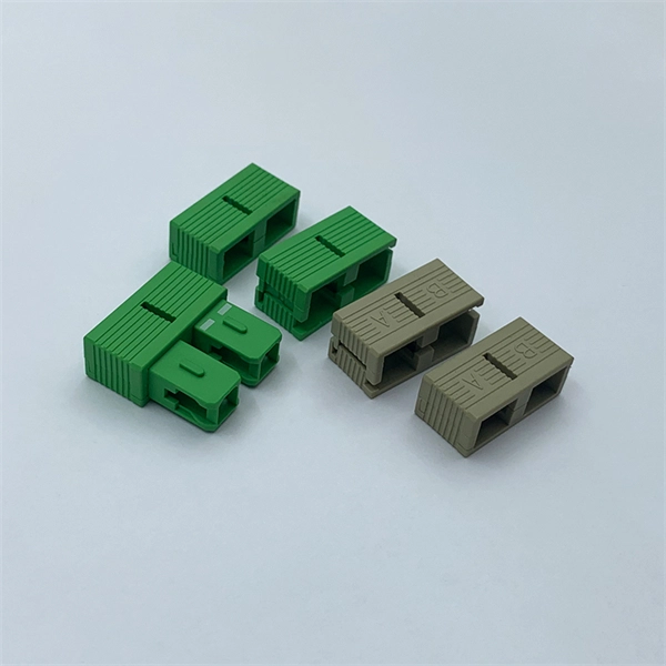
The primary function of a fiber adapter panel is to provide a housing for fiber optic adapters or connectors. These adapters act as the interface between the terminated fiber ends and the active equipment, such as switches, routers, or servers. A fiber patch panel is a mounted enclosure—either rack-mounted or wall-mounted—used to terminate, manage, and interconnect multiple fiber optic cables. It acts as a hub for organizing splices and patch cords, streamlining fiber management and preserving signal integrity. This guide will focus on elucidating the aspects of the fiber patch panel, its accessories, the work done with such a device, and how to. Fiber optic networks are the backbone of fast, reliable internet and modern communications, but even the best fiber cables need the right connectors and patch panels to work efficiently. Connectors are the points where fiber cables link to devices, equipment, or other cables, and using the right. The fiber optic patch panel, also known as the fiber distribution panel, serves as the crucial component of the management of fiber optic cables. Also, the advantage of fiber optic patch panels is to reduce the loss of fiber optic transmission and facilitate engineers to troubleshoot. Serving as the network's centralized junction, it provides secure ports for both incoming and outgoing fibers, streamlining connection.
[PDF]
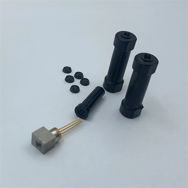
The FC connector is a fiber-optic connector with a threaded body, which was designed for use in high-vibration environments. It is commonly used with both single-mode optical fiber and polarization-maintaining optical fiber. FC connectors are used in datacom, telecommunications, measurement equipment, and single-mode lasers. They are becoming less common, displaced by SC an. DesignThe fiber end is embedded in a 2.5 mm ferrule made of ceramic or. The tip is then typically polished to produce a rounded surface, called "physical contact" polish. This surface profile means that when t. FC connectors' floating ferrule provides good mechanical isolation. FC connectors need to be mated more carefully than push-pull type connectors due to the need to align the key, and due to the risk of scratching t.
[PDF]
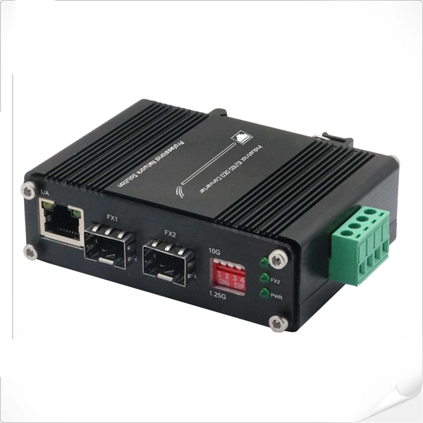
A Fiber Channel SFP is an optical transceiver module purpose-built for Fiber Channel (FC) networks, enabling dedicated, high-reliability communication between servers, switches, and storage systems in SAN environments. Fiber Optic Transmitters, Receivers, Transceivers PC, 5-5,5V, FC con. A tariff of 10 % may be applied if shipping to the United States. A tariff of 10 % may be. Fiber Channel technology (Fibre Channel) is a network storage switching technology that can provide long-distance and high bandwidth, and can realize the transmission of large data files between storage, server and client nodes. Although it shares the same physical form factor as Ethernet SFPs, a Fiber. This article provides a concise overview of FC transceivers, focusing on their core features, technical specifications, and main application scenarios to help professionals quickly grasp this essential technology and optimize storage network deployment and maintenance. With support for Fast Ethernet, Gigabit Ethernet, Fibre Channel and legacy protocols such as SDH/SONET and BiDi, SFP. Fibre Channel (FC) is a high-speed network interconnection technology (usually running at 2Gbps, 4Gbps, 8Gbps, 16Gbps and 32Gbps), which is mainly used to connect computer storage devices. In the past, Fibre Channel was mostly used for supercomputers, but now it is also becoming a common connection.
[PDF]
Multimode Fiber Optic Receivers are devices designed to interpret information contained in optical signals transmitted through multimode fibers. These receivers convert the optical signals into electrical signals, allowing the data to be processed and utilized by electronic systems. Multimode Fiber. They convert electrical signals into optical signals for transmission over fiber-optic cables and reverse the process at the receiving end. Now, the term 'multimode' stems from the fact that these transceivers use multimode fiber (MMF) cables, which can carry multiple beams of light — or 'modes' —. Multi-mode optical fiber is a type of optical fiber mostly used for communication over short distances, such as within a building or on a campus. Multi-mode links can be used for data rates up to 800 Gbit/s. Most systems operate by transmitting in one direction on one fiber and in the reverse direction on another fiber for full duplex operation. For applications where long-haul transmission is unnecessary, multimode SFP modules offer a practical. They have a wider core (around 50 to 62. 5 micrometers), which enables multiple modes or light paths to coexist within the fiber, thus resulting in modal dispersion at shorter distances but reducing its efficacy over longer stretches. The choice between Single-Mode Fiber (SMF) and Multimode Fiber.
[PDF]

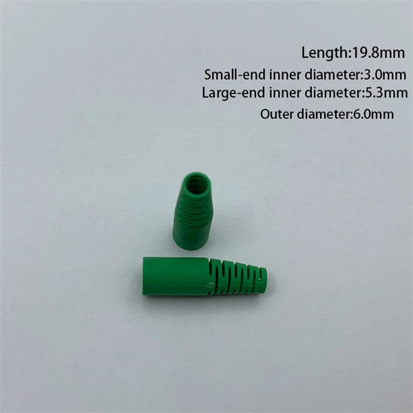
Protect fiber optic cable connections:The joint box provides physical protection for the fiber optic cable connection parts to prevent damage to the fiber optic cable caused by external environmental factors such as moisture, dust, chemical corrosion and mechanical damage. Provide a stable. Fiber optic sleeves are protective devices used for fiber optic connections. Splice protection sleeve, usually made of plastic or metal, are used to secure and protect the fusion joint between two optical fibers. Fiber Cable Joint Box is attributed to the mechanical pressure sealing joint system. Fiber Cable Joint Box is a continuous protection device for supplying optical, sealing and mechanical strength continuity between adjacent optical. The optical fiber terminal box is the terminal joint of an optical cable, one end of which is an optical cable, and the other end is a pigtail, which is equivalent to a device that splits an optical cable into a single optical fiber. The user optical cable terminal box installed on the wall, its. Fiber Optic Splice Closure is designed to protect optical fibers from debris, dirt, dust, moisture and water. As much of the fiber system is outside in a harsh environment, these fiber optic splice closures are designed to meet the tough protection requirements of fiber-optic splices. UnitekFiber. Overview Application of Optical Fiber Splice Closure/Joint Box/Joint Closure: 1. CATV environment.
[PDF]

Generator protection relays are devices that detect abnormal operating conditions and isolate the generator from the system to prevent damage. These relays act as the first line of defense and are installed with strict adherence to IEC Standard for Protection Relays. Protecting generators from different electrical, mechanical, and thermal stresses is known as generator protection. To safeguard machines from overloads and unusual circumstances, preventive measures are required. Faults are inevitable even with effective design, construction, and operation. Below is an overview of the different types of relays used in generator systems, their functions, and their specific applications. Electromagnetic relays use. Generator Protections are broadly classified into three types: Class A, B and C. Class A covers all electrical protections for faults within the generating unit in which generator field breaker, generator breaker and turbine should be tripped. What Are Generator Protection Relays? Generator protection. There are various protection relays and those are used for protection against a wide variety of conditions. The fundamental principles that are covered in this course are equally applicable to. IEEE C37. 2 defines the IEEE “numerical” function designation for all protective relay functions. This presentation primarily uses the designations from the Beckwith M-3425A relay, which in most cases follows IEEE C37.
[PDF]
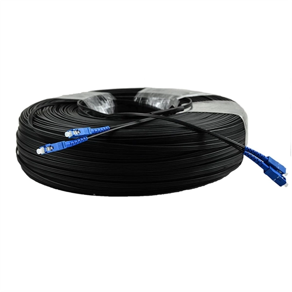
They are the bridge between fiber optic cables in the field and the equipment or patch panels that manage them. By combining factory-installed connectors with spliced bare fiber, pigtails ensure that network installers can create fast, reliable, and cost-effective terminations. Each splice tray includes one or more slots containing fusion, mechanical, or pigtail splices and single mode or modes splicing configurations. Tampering with such splice trays would render the fibers unbent and significantly reduce the network's likelihood of loss or collapse. As a result, they. Fiber pigtails are simple in appearance, yet essential in function. This article will show you what a fiber optic pigtail is. The success of a network in fiber optic cable installation heavily. This is a technology less than a decade old that combines the splice tray, adapter panel, pre-stripped and routed pigtails and splicing consumables required for optical fiber termination in a single compact cassette. In this article, we will examine the factors that have put the exciting new. A fiber optic pigtail is a type of fiber optic cable with only one end that has a factory-terminated connector and the other end exposed as bare fiber. Hence the connector side can be linked to equipment and the other side melted with optical fiber cables. Fiber optic pigtail are utilized to terminate fiber optic.
[PDF]

Connecting a multi-mode SFP to single-mode fiber creates a major signal mismatch. A small portion of the transmitted light gets captured. This leads to high attenuation and frequent link drops. I suggest you avoid such setups. Use them if essential and with proper mode. A Fiber Channel SFP is a specialized optical transceiver designed exclusively for Fiber Channel (FC) networks, enabling high-speed, low-latency, and lossless data transmission in Storage Area Network (SAN) environments. These transceivers comply with the ANSI INCITS 404-2005 Fiber Channel standard and IEEE 802. 3 for. There are two main types of fiber optic cables: single mode and multimode. Although they can do the same job in some instances, the different construction methods make each of them better suited to certain tasks and budgets. That makes picking between single mode and multimode fiber optic cables an. Single-mode (SMF) and multi-mode fiber (MMF) use different core sizes, sources and wavelengths. Understanding the compatibility constraints prevents costly downtime and troubleshooting. What Is the Difference Between Single Mode and Multimode Fiber? The main difference between these fiber options comes down to how light travels through. What is Single-mode SFP? Before we compare them, we need to know their brief definitions. A single-mode SFP is specially used with the 9/125µm single-mode fiber (SMF) but can not be used with multimode fiber cable.
[PDF]
This guide is written for embedded developers who work on connected products. That includes microcontroller based systems that operate in bare metal or RTOS mode, as well as microprocessor based system.
[PDF]
A fiber coupler is a passive optical device that manages the flow of light signals within an optical network. It functions by dividing a single incoming light path into multiple outgoing paths, or by combining light from several input paths into a single output fiber. What are some common uses of fiber couplers in fiber optics, including fiber lasers? What are dichroic couplers and how are they used in fiber amplifiers? What is the principle of evanescent wave coupling? What factors influence the coupling strength and wavelength sensitivity in fiber couplers?. This tab provides a brief explanation of how we determine several key specifications for our 1x2 couplers. This capability is fundamental. Fiber optic coupler is one type of fiber optic component that allows for the redistribution of optical signals. It covers a wide range of fiber optic devices such as optical splitters, optical combiners, and optical couplers. A fiber optic coupler is a device that can distribute the optical signal. Fiber optic couplers are optical devices that connect three or more fiber ends, dividing one input between two or more outputs, or combining two or more inputs into one output. List the types of extrinsic and intrinsic coupling losses. Understand the degree to which fiber alignment and fiber mismatch problems increase system loss. Detail the score-and-break cleaving.
[PDF]
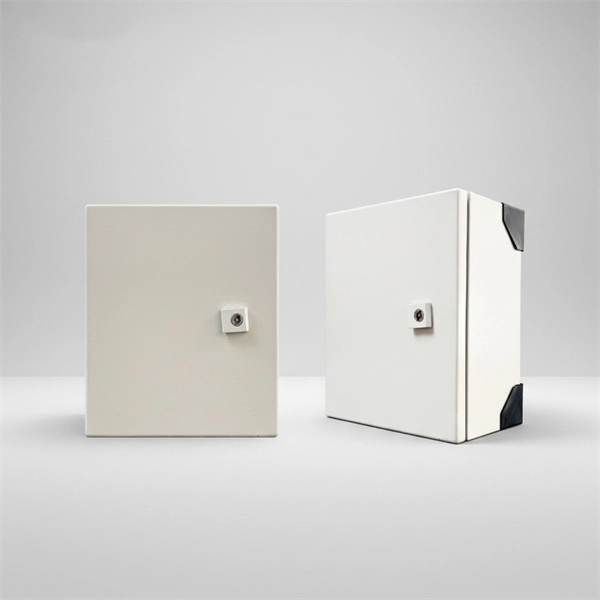
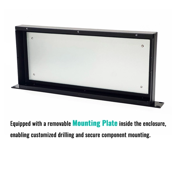
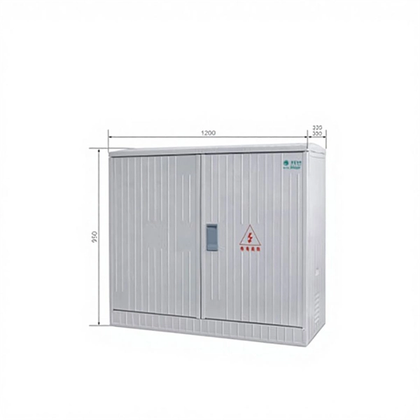
Its primary purpose is to ensure safe and efficient power distribution while providing protection via fuses or circuit breakers against overloads and short circuits. Distribution boxes are built with durable materials, typically metal or high-grade plastic, designed to endure. Most distribution boxes contain circuit breakers or fuses that function as protective barriers for the connected wiring and electrical devices. These safety components monitor the electrical flow continuously. When electrical problems occur—such as short circuits or excessive power draw—the circuit. Its primary role is to ensure safety, control, and organization. Let's break down its core functions. Centralized Control and Distribution The main function of a Distribution Box is to act as a central hub. The single, thick cable bringing power from the utility company enters this box. Inside. A low voltage distribution box safely manages and protects electrical circuits, ensuring reliable power distribution and enhanced safety in any building. It is commonly used in homes, offices, and industrial settings to control and protect electrical circuits. It helps organize, protect, and control electrical connections in residential, commercial, and industrial electrical systems.
[PDF]

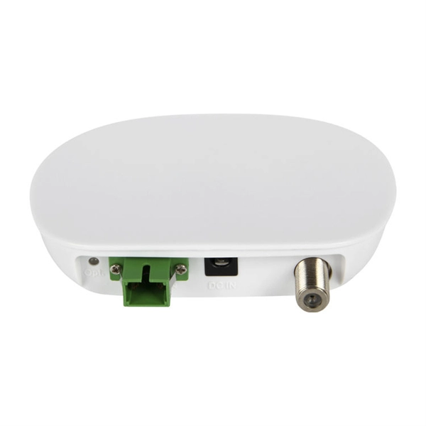
An optical coupler helps split or join light signals in a fiber network. It can take one light signal and send it to two or more places. They do not send signals to the. An Optical Splitter, also known as a beam splitter, is a passive optical device that divides a single input optical signal into two or more output signals. Unlike active devices (which require power), splitters operate without electricity, relying solely on the physics of. You use optical couplers and splitters to split or join signals in fiber networks. For example, optical splitters send light to many output ports. This lets you connect more users to one network terminal. You can also use them to join light from. Optical Distribution Network (ODN) - The physical fibre and optical devices that distribute signals to users in a telecommunications network. The ODN is composed of passive optical components (POS), such as optical fibers, and one or more passive optical splitters. Optical Network Termination (ONT). Functioning as a translator, the ONT converts optical signals from the fiber optic cable into electrical signals that your router and devices can understand. In essence, it serves as the bridge between your internet service provider's (ISP) network and your home network. This type of device plays an important role in passive.
[PDF]
The equipment is used as a termination point for the feeder cable to connect with drop cable in FTTx communication network system. The fiber splicing, splitting, distribution can be done in this box, and meanwhile it provides solid protection and management for the FTTx network. PTE 24 U. 24-Port Fiber Optic Terminal Box is widely used in Italy in conjunction with the Optotec ROE Multi-Dwelling Unit (MDU) and PTE termination box. The cabinet. The HTB8067 24 Port Indoor Fiber Optic Distribution Box is designed for clean, efficient cross-connection between outdoor backbone cables and indoor subscriber fibers. Total. Tailored for FTTH in multi-dwelling units, serving as a floor-level transition for riser and horizontal cables. Provides storage for overlength and terminated fibers along with splicing capabilities. Suitable for indoor floor installations in residential or commercial buildings. Fiber optic cables, composed of ultra thin glass or plastic fibers that transmit data as light signals, are extremely fragile. Even minor physical stress, such. The 24 port NID can load LC or SC adapters and pigtails, 1x16 or 2x16 Optical PLC Splitter. This UV resistant shell is designed.
[PDF]
A beam splitter or beamsplitter is an that splits a beam of into a transmitted and a reflected beam. It is a crucial part of many optical experimental and measurement systems, such as, also finding widespread application in.
[PDF]
It consists of a lever or knob that can be turned to switch off the power supply to a particular circuit. It works by isolating a particular circuit from its power source, making it possible to work on the circuit without any risk of electrical shocks. Rotary. Our guide focuses on rotary switches, explaining their uses, how they work, and the different types available. What is a Rotary Switch? Rotary switches can be explained relatively easily. Many devices and circuits require switches with multiple available positions, to select different electrical. The rotary switch is a type of electrical switch and a primary electromechanical device that is utilised to regulate a number of circuits by rotating the switch's actuator only. A rotary switch may be more complex than a simple switch that is designed to have only two states – on and off. There are also two types of rotary switch structure, unipolar, single-position structure and multi-pole, multi-position structure. Single-pole, single-position rotary switches are often used.
[PDF]