Indoor cable (PVC or LSZH jacket) is cheaper but unsuitable for wet or UV-exposed environments. Fiber optic cables are essential components in today's broadband, FTTx, and data center networks. Whether you're planning a national fiber rollout or sourcing cables for enterprise infrastructure, understanding how fiber optic cable pricing works can help you budget more effectively and make better. Buyers typically pay for fiber optic cable by length, fiber type, and installation complexity. Main cost drivers include cable grade (indoor vs outdoor, armoured), distance, and labor for trenching, splicing, and termination. This guide presents ranges in USD and practical price estimates to help. Optic cable price represents a crucial consideration in modern telecommunications infrastructure, reflecting the complex interplay of manufacturing costs, technological advancement, and market demand. These essential components of digital communication networks vary in price based on several key. * Disclaimer: Prices fluctuate based on raw material indices (Glass/Copper/Polymer) and cable core count (e. This feature makes them ideal for high-voltage power lines where both grounding and data transmission are needed. On the other hand, standard fiber optic cables 4 focus solely on data transmission and are.
[PDF]

Optical switches will accept inputs nearly immediately as compared to mechanical switches, which could experience a few milliseconds of debouncing lag. Since optical switches do not depend on physical contact, input latency (latency) is severely minimized. This discrepancy can just be a couple of. An optical transistor, also known as photonic transistor, optical switch or light valve, is a device that switches or amplifies optical signals. Any communication protocol (Ethernet, ATM, etc. Significant. High Speed: Optical switches provide a high-speed data transmission capacity that surpasses that of traditional electrical switches. Interference Resistance: They are immune to electromagnetic interference, ensuring a reliable data transfer. Low Power Consumption: With no need for O-E-O conversion. Optical switching is the process of controlling the destination of individual optical information signals. This technology allows for high bit rate transmission to be switched between various optical lines. The core component enabling optical switching is the Optical Switch. Figure: Optical Switch. Serving as the backbone of high-speed fiber-optic networks, data centers, and emerging technologies like quantum communication, optical switches enable efficient light signal management with a small latency. As global demand for bandwidth surges due to 5G, AI, and cloud computing, advancements in.
[PDF]

IEC 60793-1-40:2019 is available as IEC 60793-1-40:2019 RLV which contains the International Standard and its Redline version, showing all changes of the technical content compared to the previous edition. IEC 60793-1-40:2019 establishes uniform requirements for measuring the. All Rights Reserved. fCONSTRUCTION QUALITY REQUIREMENTS FOR FTTP & SSP Work Orders This document provides Construction Technicians, Construction Managers, FTTP/SSP Vendors, and Inspectors with the essential information to ensure a quality build and to successfully pass an Outside Plant Inspection. Four methods are described for measuring attenuation, one being that for modelling spectral attenuation: -method D:. The first ITU-T Handbook related to optical fibres, Optical Fibres for Telecommunications, was published in 1984, and several others have been produced over the years. This Standard may also apply to the Jet Propulsion Laboratory other contractors, grant recipients, or parties to agreements PR 8735. 2, Hardware Quality Assurance Program Requirements for Programs and Projects. Use. Note: This list was assembled from a number of sources with various dates - we doubt it is complete because they change all the time. A full catalog of TIA specs is at org/ Learning More About Standards and Codes There are a number of ways of finding out more about cabling.
[PDF]
Recommendation ITU-T G. 654 describes the geometrical, mechanical and transmission attributes of a single-mode optical fibre and cable which has the zero-dispersion wavelength around 1300 nm wavelength, and which is loss-minimized and cut-off wavelength shifted at around the 1550 nm. Recommendation ITU-T G. 649 Optical fibre cables G. 659 Characteristics of optical components and subsystems Characteristics of optical systems G. E fibre: empowering ultra high-capacity long-haul transmission. Sumitomo Electric. TRANSPORT A S ACCESS NE around the 1550 nm wavelength region. This is the latest revision of this Recommen. ata rates at and above 800 Gb/s over distances further than a few hundred kilometres. Over longer distances, such as between two data centres, signal regeneration or addition ng-distance transmission,” said Xavier Renard, Telecom Marketing Di ector at ACOME. “It's also c ucial that we consider the. ACOME Group and Sumitomo Electric Industries, Ltd. have announced a new proposal for long-haul optical network cables that will 'break through the glass ceiling' of data transmission limits to ensure the ever-growing demands of data centres can be supplied. To support these high capacity systems in terrestrial backbone networks, low attenuation and large core area fibers compliant with Recommendation ITU-T G 654. E were introduced and have been extensively deployed worldwide.
[PDF]

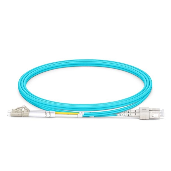
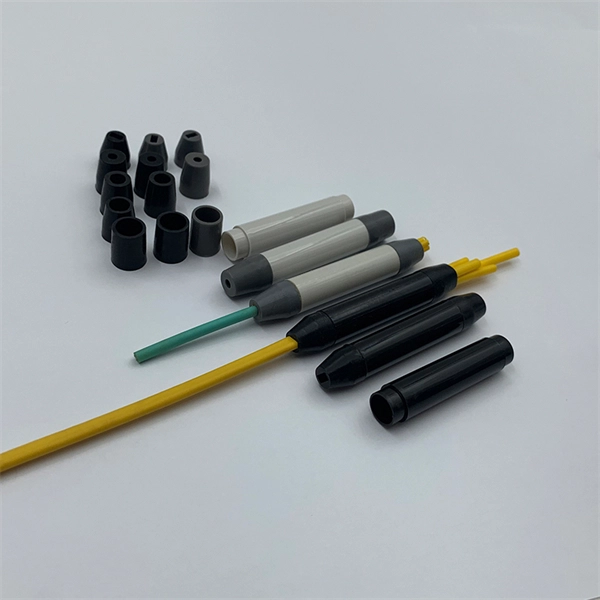
As fiber optic cables are generally only produced in lengths up to around 5 km, so when lengthier connections are needed, splicing two cables together becomes necessary. So in essence, fiber optic splicing is a process used to join two separate fiber optic cables together. There are numerous use cases for fiber optic splicing. As. The time it takes to splice a fiber optic cable can vary depending on several factors, including the type of splice, the equipment used, and the level of expertise of the technician performing the splice. Proper termination is essential for ensuring optimal performance, reducing signal loss, and maintaining the durability of the connection. Another method of connecting optical fibers is termination or connectorization, which consists of processing the end of a fiber optic bundle so that it can be connected to other fibers or devices through fiber optic. Fiber optic joints or terminations are made two ways: 1) splices which create a permanent joint between the two fibers or 2) connectors that mate two fibers to create a temporary joint and/or connect the fiber to a piece of network gear. Either joining method must have three primary characteristics.
[PDF]

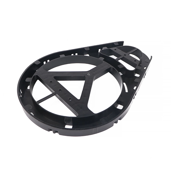
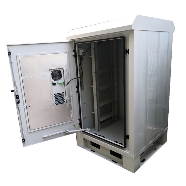
Here's a step-by-step guide to help you set up your fiber distribution box seamlessly: Before installing the fiber distribution box, ensure that your optical cables are properly prepared for connection. The optical fiber distribution box allows people to easily access the optical fibers in the box, and can well protect the optical fibers. In addition, the drawer structure also facilitates high-density wiring and good cable management. However, because optical fibers are fragile and can be easily. Keeping this page as a placeholder for now. Have any questions? Talk with us directly using LiveChat. Fix the rack to the ground with expansion bolts. Top installation: Dimensions of four connection holes on the top according to the. This instruction describes the installation of the Fiber Distribution Frame (FDF) manufactured by Corning Optical Communications. To order accessories that are purchased separately, contact Corning Optical Communications customer care for assistance. Read and understand this procedure (as well as. Optical fiber distribution frame is the wiring connection equipment between optical cable and optical communication equipment or between optical communication equipment. Distribution boxes are especially essential for FTTH networks, where they enable the efficient connection and management of optical fibers from a central.
[PDF]
Glass fiber and plastic fiber is fragile. When individual fibers break, light transmission and uniformity are reduced. After the first few fibers break at a stress point, a chain reaction occurs, hastening t.
[PDF]

An optical transceiver module, often simply called an optical module, acts as a signal conversion interface in fiber optic networks. It transforms high volumes of electrical signals into optical signals for transmission over fiber cables, or reverses the process at the receiving. In the world of fiber optic communications, optical transceiver modules play a pivotal role as interfaces that convert electrical signals to optical signals and vice versa. If you're dealing with data centers, telecommunications, or AI networking, grasping the key parameters of an optical. Optical transceivers are efficient in changing signals. These modules have many parts, each with a specific functions: Takes in electrical signals to change them. Powers lasers or LEDs to send light signals. Combines many light signals into one for. An optical transceiver, a crucial device utilized in optical communication, is an optoelectronic element, allowing the interconversion of optical and electrical signals during the information transmission. Acting as the "heart" of fiber-optic networks, these modules—ranging. This comprehensive guide breaks down the internal structure, core components (TOSA, ROSA, lasers), and operational mechanisms of SFP optical modules, enriched with technical insights and real-world applications.
[PDF]

Optical Modules Market Segments - by Product Type (Transceivers, Receivers, Transmitters, Amplifiers, and Others), Application (Data Centers, Telecommunication, Enterprise Networking, and Others), Distribution Channel (Online Stores, Direct Sales, Indirect Sales . Optical Modules Market Segments - by Product Type (Transceivers, Receivers, Transmitters, Amplifiers, and Others), Application (Data Centers, Telecommunication, Enterprise Networking, and Others), Distribution Channel (Online Stores, Direct Sales, Indirect Sales . Data centers will keep dominating optical module demand as AI and cloud drive revenue growth through 2030. Optical module demand is being pulled in two directions at once, faster bandwidth for dense networks and tighter constraints on power, security, and lead times. 8% during the forecast period 2025-2031. The potential shifts in the 2025 U. tariff framework pose substantial volatility. The Optical Module Market size was estimated at USD 26. 53 billion in 2025 and expected to reach USD 30. The accelerating explosion of global data traffic has thrust optical modules into the heart of modern communications.
[PDF]

An Optical Splitter, also known as a beam splitter, is a passive optical device that divides a single input optical signal into two or more output signals. Conversely, it can also combine multiple signals into one. Knowing the difference between a splitter and an optical coupler helps you build better networks. You make your network work better when you pick the right device for each job. You can connect many users to one port with 1:n or 2:n splitters. By dividing a single optical signal from a central Optical Line Terminal (OLT) into multiple outputs for Optical Network Terminals (ONTs) at users' homes, splitters eliminate the need for dedicated fibers to each residence—slashing infrastructure costs while scaling network reach. This guide. In a Passive Optical Network (PON), a single optical fiber carries massive amounts of data using light. Signal Input: The fiber splitter receives the optical signal from the upstream network node and enters the splitter through the input fiber. Signal Distribution: Inside the splitter, according to the design structure and different. Splitters are passive optical devices that divide or combine optical signals, and they come in various types, including power splitters, uneven splitters, and wavelength-division multiplexing (WDM) splitters. Each type serves specific applications, enabling efficient use of optical infrastructure.
[PDF]

A ceramic sleeve is a small, cylindrical element employing zirconia, which is a strong, low thermal expanding ceramic used in a fiber optic system to locally align and hold the interface between the fibers or connectors. It ensures precise alignment. Known for their high-temperature resistance, wear resistance, and chemical stability, ceramic sleeves have become a key element in applications spanning communications, electronics, automotive, aerospace, and industrial systems. The industry is developing in a diversified manner, connecting raw. Most of the ferrules used in optical connectors are made of ceramic (Zirconia) material due to some of the desirable properties they possess. Kyocera's extrusion molding process creates ferrules with excellent coaxiality, and our precision machining ensures excellent concentricity with precise. Alignment sleeves are the primary mechanical reference inside a fiber optic adapter. Their role is to constrain lateral offset, angular deviation, and axial separation between mating ferrules, directly determining insertion loss and return loss stability. Historically, both ceramic and phosphor. The global market for ceramic sleeves is experiencing robust growth, projected to reach an estimated $287 million by 2025. This expansion is fueled by an impressive CAGR of 20. 5% during the study period. The primary drivers for this surge are the increasing demand for high-performance optical.
[PDF]

However, there are still some scenarios where an optical drive is necessary or desirable. What is an Optical Drive?. THe Optical memory is an electronic storage medium that uses a laser beam to store and retrieve digital (binary) data. In optical storage technology, a laser beam encodes digital data on an optical disc or laser disc in the form of tiny pits arranged in a spiral pattern on the surface of the disc. In this article, we'll explore the pros and cons of having an optical drive and help you decide whether you need one. Although a number of optical formats have been used over time, the most common examples are optical discs such as the compact disc (CD) and the digital versatile disc (DVD). The primary components of an optical drive include a laser, a lens system, a motor for spinning the disc, and a decoder to interpret the data. It is commonly found in computers, laptops, and gaming consoles. Optical drives are essential for installing software, playing movies, and backing up data.
[PDF]
Shop cable conduit and interduct for fiber and network cable protection. Ideal for both indoor/outdoor use, this product is easy to install. 1" PVDF Plenum Rated Fiber Innerduct Snap Coupling (for F1-11437 and F1-11437S only). Corrugated, smooth or split wall types. Fiber cable tray/duct is designed to protect and route fiber optic patch cords, multi-fiber cable assemblies, and intrafacility fiber cables (IFC) to and from fiber splice enclosures, fiber distribution frames and fiber optic terminal devices. Our fiber duct/tray is manufacturder with fire. Innerduct is used to protect fiber optic cables as they are routed through buildings or underground. Inner duct product line consists of corrugated HDPE, riser rated PVC and plenum rated PVDF. UL 2024 listed and among the most flexible flame-rated Inner duct products on the market. These ducts are essential for maintaining signal integrity, preventing physical damage, and ensuring long-term reliability in various environments. PVC innerduct conduit is non-metallic, lightweight, corrugated, and flexible to protect and route electrical wire and cables. Note: Product availability. 1-1/4" Diameter, Corrugated HDPE (High Density Polythylene) Innerduct, Orange. Includes: Pull String. No UV Protection, not suitable for outdoor use. Category: Corrugated.
[PDF]
Fiber optic cables use total internal reflection to keep light signals bouncing within the core, allowing data to travel quickly and with minimal loss. An optical fiber is comprised of a light-carrying core in the center, surrounded by a cladding that acts to traps light in the. Optical fibers are thin glass rods that use the properties of light reflection and refraction to transmit data over long distances. They actively shuttle data encoded in pulsing light across vast distances using only subtle differences in materials. They consist of three elements as shown in Figure 1: a central core, cladding and a protective coating. Optical fibers operate on the principle of total internal reflection, which. Refraction and total internal reflection (TIR) are the two fundamental optical principles that allow light to propagate through optical fibers over long distances with minimal loss. Understanding these mechanisms is essential for designing, installing, and troubleshooting fiber networks in FTTH. Fiber optic cables use a similar concept to guide light. Fiber optic. Describe the workings and uses of fiber optics. Analyze the reason for the sparkle of diamonds. A good-quality mirror may reflect more than 90% of the light that falls on it, absorbing the rest.
[PDF]

Key finding: This paper develops analytical models and design procedures of ultra-wideband Wilkinson power dividers using linearly tapered transmission lines (TTLs) which provide size reduction and broadband performance. Read more. Power dividers are the passive electronic equipment used for splitting the power. They are now being employed in a variety of communications applications such as telephonic, antennas configurations, mobile connectivity, internet technology, & optics, etc. They come up with very low loss, operate at. RF and microwave power splitters and dividers create two copies of the same signal, while ideally preventing crosstalk between the outputs. Doing this with minimal loss while maintaining signal integrity is a challenge. In this article we explain how power splitters work and what the tradeoffs are. The rise of wireless connectivity requirements for applications such as Internet of Things (IoT), cellular, and automotive electronics is resulting in systems that are increasingly using RF signals, components, and subsystems. Often, designers need to direct these signals to more than a single. A power divider is a passive electronic device used in radio frequency (RF) and microwave applications to split an input signal into multiple output signals with equal or specified power levels, while maintaining impedance matching to minimize signal reflection and loss. How can power dividers.
[PDF]
