will introduce major upgrades to its Multi-Rail technology platform at ECOC 2025, targeting hyperscale optical transport with new efficiency, scale, and performance enhancements. Coherent Corp. SAXONBURG, PA, September 26, 2025 (GLOBE NEWSWIRE) – Coherent Corp. At the heart of the. SAXONBURG, Pa. At the heart of the. Simultaneously, coherent technology has emerged as the prevailing solution for Data Center Interconnection (DCI) applications, covering distances of 80~120km in the field of data communication. These evolving applications introduce new demands for coherent optical transceiver systems, steering the. Coherent optical module refers to a typically hot-pluggable coherent optical transceiver that uses coherent modulation (BPSK / QPSK / QAM) rather than amplitude modulation (RZ/ NRZ / PAM4) and is typically used in high-bandwidth data communications applications. Optical modules typically have an.
[PDF]

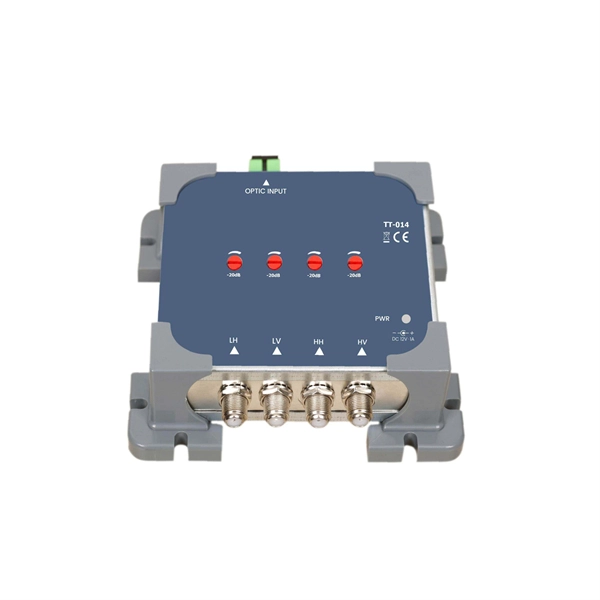
Explore our comprehensive SFP optical module selection guide for 2025. Learn about crucial factors like data rate, distance, fiber type, and compatibility to optimize your network performance and cost-effectiveness. Make informed decisions for your networking needs today!. SFP (Small Form-factor Pluggable) is a compact, hot-pluggable network interface module used to connect network devices (switches, routers, firewalls) to fiber optic or copper cables. They're essential for extending network distances and increasing bandwidth capabilities. Selecting the correct SFP module is not simply a matter of matching connectors. In modern Ethernet networks, choosing the wrong transceiver can result in link failures, speed mismatches, compatibility errors, or unexpected distance limitations. For network engineers, system integrators, and IT. At the core of these advanced networks are bidirectional SFP modules, also known as BiDi SFP transceivers—compact, cost-efficient devices that support high-speed data transmission and reception over a single optical fiber. By using different interfaces and single-mode or multimode fiber depending on the.
[PDF]
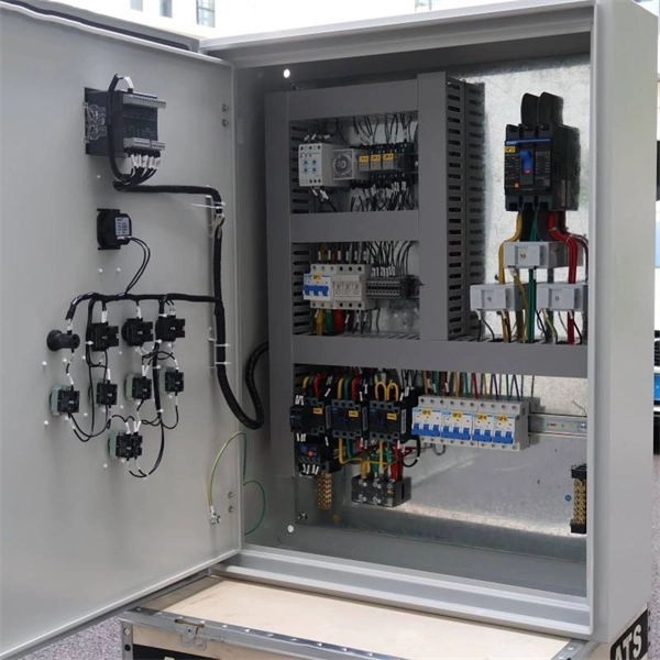
Look at key criteria like power needs, equipment type, installation conditions, safety, compatibility, quality, cost, layout, and certifications. Use practical checklists to help you make a confident decision. Calculate your total power demand before choosing a distribution. Choose the right low voltage distribution box by matching capacity, safety, and environment to your needs for reliable and efficient electrical protection. com) lists GE low voltage circuit breakers and the short circuit current to which they are selective. DET-537 includes legacy products. Designing Low Voltage (LV) and Medium Voltage (MV) electrical systems is a critical task that requires precision, knowledge, and strict adherence to international standards. The IEC (International Electrotechnical Commission) standards provide a comprehensive framework to ensure safety. Short circuit studies determine fault current levels throughout the system. This data guides protective device selection. Proper coordination prevents nuisance tripping during faults. This chapter explains the main electrical and environmental characteristics to take into account, proposes some guidelines. The safety and efficiency of an electrical system depends on the selection of an LV (Low Voltage) distribution box. The decision is influenced by numerous criteria, including but not limited to technical requirements, environmental specifications, security measures, and general product quality.
[PDF]
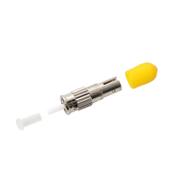
In this comprehensive guide, we'll walk through the best practices for installing various types of fiber optic cable, from patch cords to distribution fiber, and provide practical tips to ensure a successful installation. Correct patch-cord installation is essential for maintaining low insertion loss, stable return loss, and long-term reliability in both indoor and outdoor fiber networks. Proper handling, routing, cleaning, bend-radius management, and connector alignment ensure that the optical link meets design. Proper installation and regular maintenance of fiber optic patch cords play a crucial role in achieving optimized network performance, preventing signal errors, and extending service life. This guide addresses expert-certified best practices applied by professionals in the telecommunications, data. Proper connection of fiber optic cables is essential to harness these benefits fully, as even minor errors can lead to significant performance issues like signal loss. Whether you're connecting a data center, a corporate network, or a high-density fiber infrastructure, correct installation methods are essential. Yingda. In today's high-performance networks, fiber optic patch cables are the lifelines that ensure smooth data flow across switches, servers, and routers. Even the most advanced optical transceivers can only perform at their peak when paired with properly installed, clean, and precisely managed fiber.
[PDF]
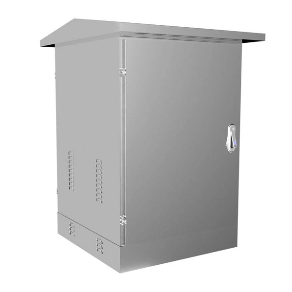
The vertical distance between the bottom surface of fixed distribution box and switch box and the ground shall be greater than 1. 3m and less. Flameproof enclosure (Ex d IIB+H2), which can be used as feed distribution equipment in control and distribution system (such as distribution box, switch box of main circuit, control box, terminal box or motor starting box etc. ) ·Enclosure: stainless steel. Equipped with specialized hinge. The Unified Facilities Criteria (UFC) system is prescribed by MIL-STD 3007 and provides planning, design, construction, sustainment, restoration, and modernization criteria, and applies to the Military Departments, the Defense Agencies, and the DoD Field Activities in accordance with USD(AT&L). Structural requirements for explosion-proof distribution boxes: 1. The. Explosion-proof distribution boxes aren't just metal containers; they're engineered life-savers designed to contain potential disasters before they start. When lives and million-dollar facilities hang in the balance, you don't want generic solutions. These specialized enclosures are built tougher. The Code of Federal Regulations (CFR) is the official legal print publication containing the codification of the general and permanent rules published in the Federal Register by the departments and agencies of the Federal Government. The Electronic Code of Federal Regulations (eCFR) is a.
[PDF]

The codes in Box 7 of your Form 1099-R indicate the type of distribution you received. Distributions from a governmental section 457(b) plan to a participant or beneficiary include all amounts that are paid from the plan. For more information, see Notice 2003-20 on page 894 of Internal Revenue Bulletin (IRB) 2003-19 at IRS. gov/pub/irs-irbs/irb03-19. Enter the information from your 1099-R exactly as. Use Code 1 only if the participant has not reached age 591/2, and you do not know if any of the exceptions under Code 2, 3, or 4 apply. However, use Code 1 even if the distribution is made for medical expenses, health insurance premiums, qualified higher education expenses, a first-time home. The IRS is permanently retiring the FIRE system. All electronic information return filing will move to IRIS (Information Returns Intake System). If you currently file through FIRE, you must transition to IRIS before the deadline. These 1099r codes descriptions are taken directly from the back of form 1099-R. Early distribution, no known exception (in most cases, under age 59½). Death – regardless of the age. The following tables contain 1099 Box Numbers. These numbers are assigned to vendors on the Maintain>Accounts Payable>Vendors>1099 Information tab.
[PDF]
Return-to-zero (RZ or RTZ) describes a line code used in telecommunicationssignals in which the signal drops (returns) to zero between pulses. This takes place even if a number of consecutive 0s or 1s occur in the signal. The signal is self-clocking. In digital communication systems, line encoding schemes are crucial for representing binary data efficiently and reliably. RZ (Return-to-Zero), NRZ (Non-Return-to-Zero), CRZ (Chirped Return-to-Zero), and CSRZ (Carrier-Suppressed Return-to-Zero) are distinct line coding methods, each with its own. Abstract—Analytical formulas for the power spectra of return-to-zero (RZ) optical signals generated by Mach–Zehnder (MZ) modulators are derived. This means that a separate clock does not need. The experiment aim of this experiment is to analyze the operation of Non-Return to Zero(NRZ), Return to Zero(RZ) and Pulse ration encoders and decoders. The setup created in OptSim is shown below: Each link.
[PDF]