If a wire mesh cable tray is supporting cable with a built-in equipment grounding conductor or control or signal cables, then the tray should have a low impedance path to a non-system ground to reduce noise and remove induced or stray currents. Cable tray may be used as the Equipment Grounding Conductor (EGC) in any installation where qualified persons will service the installed cable tray system. There is no restriction as to where the cable tray system is installed. The metal in cable trays may be used as the EGC as per the limitations. Cable tray systems have become an essential component in the infrastructure of modern commercial buildings, smart offices, data centers, and various industrial facilities. These systems provide an efficient and adaptable solution for managing a wide range of cables, including power cables, control. Cable tray grounding wire is the safety connection that links your electrical system's cable tray to the ground. This provides a safe path for any stray electrical currents to flow safely into the earth, avoiding damage to your equipment and reducing the risk of electric shocks. The main purpose of. Do Cable trays have to be grounded? It sounds like a dumb question but if a cable tray has no individual wires in it only raceways, it is not likely to get energized. It involves connecting cable trays to the facility's grounding system, providing a low-impedance path for fault currents and protecting personnel.
[PDF]

This section explains that Article 250 focuses on general grounding and bonding electrical installation requirements, including: The grounding of systems, circuits, and equipment. Which circuit conductor must be grounded. Learn about the general requirements for grounding and bonding in line with the NEC 2023. The purpose of grounding is the safety of people and property. Grounding and bonding limit overvoltages, stabilize the voltage to the ground during regular functioning, and ease the proper operation of circuit. Electrical grounding is the process of connecting the non-current carrying parts of your home's electrical system—like metal boxes and appliance chassis—to the earth. In the event of a fault, such as a live wire touching a. Correct grounding of services depends upon understanding the definition and role of the grounded conductor. The neutral conductor is typically the grounded conductor connected to the system's neutral point, carrying current under normal operation. Grounding electrode conductors must be connected at. Properly grounding an electrical panel is one of the most critical safety measures in any home's electrical system. It is a non-negotiable requirement for protecting against severe electrical shocks, preventing electrical fires, and safeguarding sensitive electronics from power surges. The main goal of grounding is to limit voltages caused by lightning, line surges, or accidental contact with.
[PDF]

An Optical Splitter, also known as a beam splitter, is a passive optical device that divides a single input optical signal into two or more output signals. Conversely, it can also combine multiple signals into one. Knowing the difference between a splitter and an optical coupler helps you build better networks. You make your network work better when you pick the right device for each job. You can connect many users to one port with 1:n or 2:n splitters. By dividing a single optical signal from a central Optical Line Terminal (OLT) into multiple outputs for Optical Network Terminals (ONTs) at users' homes, splitters eliminate the need for dedicated fibers to each residence—slashing infrastructure costs while scaling network reach. This guide. In a Passive Optical Network (PON), a single optical fiber carries massive amounts of data using light. Signal Input: The fiber splitter receives the optical signal from the upstream network node and enters the splitter through the input fiber. Signal Distribution: Inside the splitter, according to the design structure and different. Splitters are passive optical devices that divide or combine optical signals, and they come in various types, including power splitters, uneven splitters, and wavelength-division multiplexing (WDM) splitters. Each type serves specific applications, enabling efficient use of optical infrastructure.
[PDF]

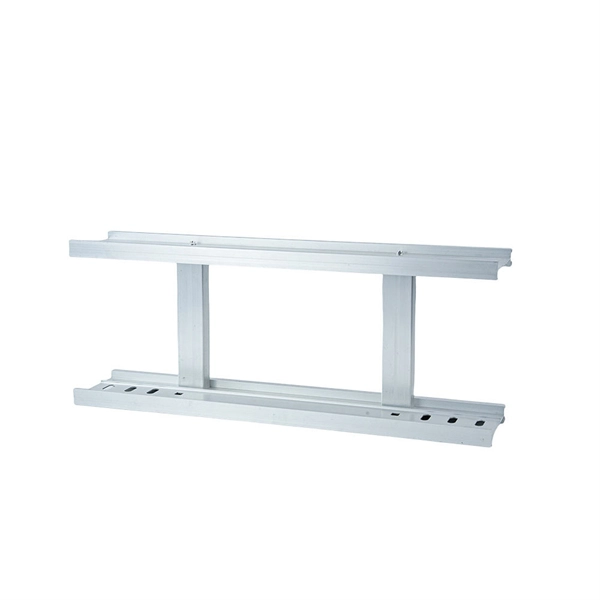
Cable Trays* — Max two 24 in. (610 mm) wide by max 6 in. (151 mm) deep open-ladder cable tray with channel-shaped side rails formed of 0. 54 mm) thick aluminum or min 0. In practice, cable tray dimensions are a system of interrelated measurements —width, depth, length, and material thickness—that directly affect cable fill compliance, heat dissipation, structural loading, and long-term expandability. From an engineering standpoint, cable tray dimensions are not. Perforated Cable Tray System expertly constructed from high-grade stainless steel, offering exceptional durability and resistance to corrosion. With side height 100mm. A properly designed and installed cable tray system will provide. Studs — Wall framing to consist of wood studs or channel shaped steel studs. Wood studs to consist of nom 2 by 4 in. Additional studs shall be used to completely frame. Best Size: Here, deep trays (75mm to 150mm) are used since power cables are typically thick and heavy. Data cables, such as your Wi-Fi or computer ones, are extremely sensitive. They do not get hot; however, they do not like to hang or sag. In case a data cable folds in an excessive manner, the. ect the minimum bend ra-dius for cables as they exit the bottom of the cable tray. A rung spacing of 6 to 9 inches (150 to 230 mm) is preferable when the cable tray cont d for instrumentation and control applications that require additional protec eferred to support and protect numerous small.
[PDF]

The OPM 510 and 520 are available in standard and high-power versions for the Telco and MSO markets. The OPM510 and OPM520 supports wavelengths of 850, 980, 1270 1300, 1310, 1490, 1550, 1577, 1623 and 1650nm. The rugged enclosure provides confidence when testing singlemode and. Count on Tempo Communications Optical Power Meters (OPM510/520) to test and maintain your fiber optic networks. Our optical power meters feature built-in calibration factors. Optical power meters and detectors have been served by Newport for over 30 years. The offering ranges from a low cost, hand-held meter to the most advanced dual channel benchtop power meter available in the market. Our 1936-R/2936-R series boasts state-of-the-art analog boards with a whopping 250. © Copyright© Santec Holdings Corporation. Demo the full range, from multi-use to dedicated PON and FTTH. VIAVI offers fast, cost-effective, and easy-to-use power meters for installation and maintenance of single mode and multimode fiber optic networks and. AFL is a trusted supplier of optical testing equipment with more than 30 years of experience and tens of thousands of units in use in the field. AFL's full range of power meters are used for testing single-mode and/or multimode fiber networks. Power meters with wave ID can detect two or more.
[PDF]

Find certified telecom, fiber optic, and copper cable splicing contractors in Georgia. Browse the SpliceList directory for verified splice crews. From homes to businesses, Comlink Solutions delivers reliable and efficient fiber optic infrastructure tailored to your specific needs. Our team of experts provides comprehensive services, from design and planning to splicing and installation. Trust us to deliver exceptional results. Over 30 years of expertise powering the nation's largest telecom networks. Turnkey fiber optic solutions from construction to testing — delivering excellence at every stage of the network lifecycle. FiberNexxt Communications, based in Marietta, Georgia, near Atlanta, is one of the area's experienced fiber splicing companies. We specialize in projects too small for large contractors and provide post-project support. Click the button below to get started. Professional fiber optic splicing services in Georgia with complete OSP overhead construction, strand deployment, pole engineering, splicing, testing, and full QA processes engineered to support telecom, ISP, and municipal broadband expansion across the state. Tired of fiber connectivity issues slowing down your business? Our expert fusion splicing services deliver rock-solid, high-speed connections for offices, warehouses, and data centers across Georgia and Atlanta. Slow internet again? Dropped connections during critical operations? Poor quality fiber.
[PDF]

In a metal box, a wire type equipment grounding conductor can be attached to the box with a ground screw or clip and terminated to the switch or receptacle in the box. Connecting the receptacle grounding terminal to the metal box ensures an effective ground-fault current path. The basic rule achieves this through an equipment grounding jumper; four exceptions. A main bonding jumper is required to bond the service disconnect enclosure to the service neutral conductor [250. Not all boxes are metal or provide. The main bonding jumper bonds the neutral conductor to the equipment grounding conductor, enabling proper operation of overcurrent protective devices. Neutral conductors must be properly sized based on the load and installation method, with specific requirements for conductors in parallel or. According to the National Electrical Code (NEC), this connection is made between the grounded conductor (typically the neutral) and the equipment grounding conductor (EGC) system at the service equipment. Proper location and sizing are not just best practices; they are essential for ensuring that. NEC Article 250 is dedicated entirely to grounding and bonding, outlining the specific conductors and connections required. Grounding Electrode Conductor (GEC): This is the wire that connects the grounding electrode (the rod) to the grounding bus bar in the main electrical panel.
[PDF]