The ASTM D6344 standard is intended to evaluate the ability of packaging to resist the force of concentrated impacts from outside sources, such as those encountered in various modes of transportation and handling. Damage to enclosures can impair the function of the equipment installed within (e. the con-trol systems of machines) or even, in the worst case, render it non-functional. Accordingly, in addition to IP protection (protection against dust, contact and water), enclosures must also have an adequate. 4. This test method is intended to determine the ability of packaging to protect. The first digit is our shield against these invaders: IP5X (Level 5): Dust-resistant—keeps out most particles but not completely dust-tight. Perfect for urban events or lightly dusty areas. IP6X (Level 6): Dust-tight—absolute protection against fine powders and particles. Essential for quarries or. Please review the permitted and restricted actions below: Standard Test Method for Concentrated Impacts to Transport Packages 1. 1 This test method covers procedures and equipment for testing complete filled transport packages for resistance against concentrated low-level impacts typical of those.
[PDF]

First, inspect the optical module appearance for physical damage, cracks, missing components, poor solder joints, or burn marks. Next, compare voltage, resistance, and waveform parameters between a normal it and the suspected faulty one, both in powered and unpowered states. As core components of optical communication systems, the proper installation and use of optical modules directly impacts network stability. This article systematically identifies common anomalies during optical module installation. However, during installation and daily operation, various issues may arise. The following will introduce the causes of various problems and how to deal with them. Optical module method/step 1. During the test, the value of the module I BiasADC is 0, and the TXLOP-ADC and. These compact devices convert electrical signals to optical signals and vice versa, enabling data transmission over fiber optic cables. While generally reliable, failures do occur, leading to frustrating downtime, performance degradation, and costly troubleshooting. This comprehensive guide details. Have you ever dealt with sudden network drops from faulty optical modules? Issues like this cannot only break communications, but they can really jeopardize business continuity.
[PDF]
AFL Mexico and South America offers fiber optic cable, transmission and substation accessories, outside plant equipment, connectors, fusion splicers, test and inspection equipment. Identify and compare relevant B2B manufacturers, suppliers and retailers Max. The company offers training in real-world scenarios with experts, both virtually and in-person, focusing on fiber optic installation and network design. They provide certification and have expertise in optical splicing. [June 12, 2024 – Guadalajara, Mexico] Test Research, Inc. (TRI), the leading Test and Inspection systems provider for the electronics manufacturing industry, recently opened a new office in Guadalajara, Mexico, to accommodate the industry's rapid growth. TRI's expansion in Mexico emphasizes its. On August 8th, operations commenced at Yangtze Optics Mexico Cable S. in Mexico's Jalisco State, marking the establishment of Yangtze Optical Fibre and Cable Joint Stock Limited Company's (YOFC) first production facility in the nation. This development not only represents a significant. Minqing Fibramerica Technology, under its trade name FIBRAMÉRICA, is one of the world's leading companies dedicated to the design, development, manufacture, distribution and marketing of advanced optical connectivity solutions. We work closely with the main players in the telecommunications market.
[PDF]

Run the loopback-detect untagged mac-address ffff-ffff-ffff command in the system view to broadcast BPDUs for loopback detection and prevent them from being terminated by unexpected devices. Huawei's comprehensive portfolio of products and solutions enables you to realize smooth digital transformation and rapid growth of virtualization, Big Data, and cloud services. Huawei switches already help customers achieve success in industries such as finance, Internet, retail, education. Plan the network configurations, configure loop prevention protocols, and enable loopback detection to prevent loops. They provide ultra-high-density 10GE/40GE/100GE/200GE/400GE full-rate access ports, meeting customers' requirements for quickly building campus networks with a simplified. CloudEngine S12700H series switches are Huawei's next-generation modular core/aggregation switches designed for high-end campus networks in the all-wireless era of Wi-Fi 6/7. CloudEngine S12700H series switches come in two models, which offer four and eight LPU slots, respectively. The S9700 uses an advanced multilayer switching architecture to support sustained bandwidth upgrading and to provide 40GE. This document provides campus networks typical configuration examples and feature typical configuration examples. "Campus Networks Typical Configuration Examples" provides typical campus network networking modes and a variety of deployment examples.
[PDF]
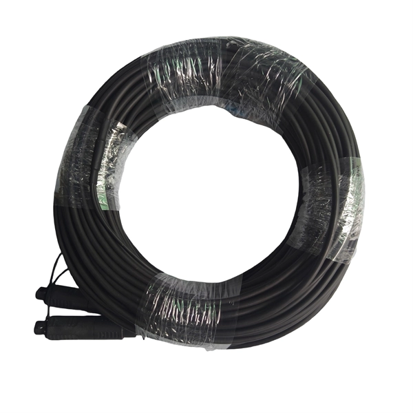
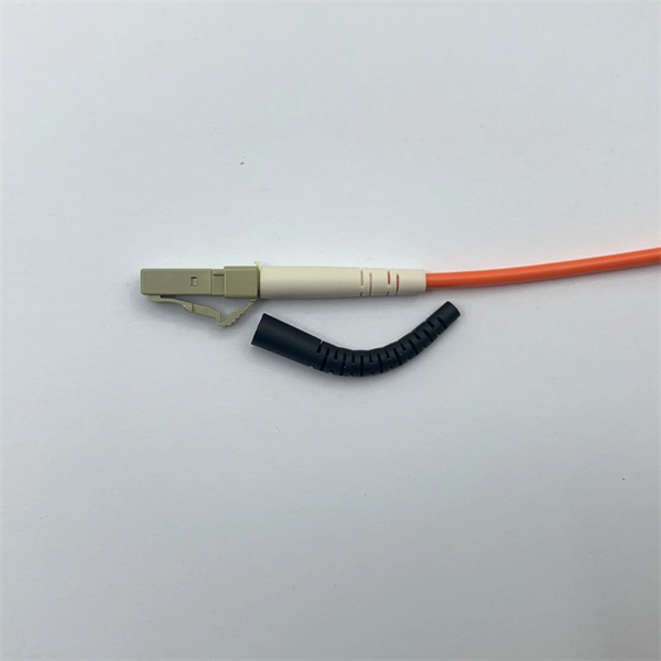
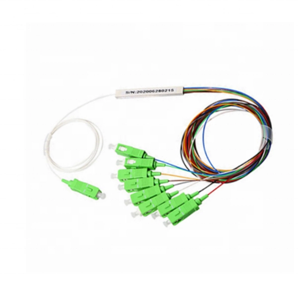
A fiber optic pigtail is a short length of optical fiber —typically 0. 5m to 2m—that has a factory-terminated connector on one end and bare fiber on the other end. The connector end is polished and tested under factory conditions, ensuring low insertion loss and high return loss. They are the bridge between fiber optic cables in the field and the equipment or patch panels that manage them. By combining factory-installed connectors with spliced bare fiber, pigtails ensure that network installers can create. The most urgent stage of the process is, in fact, separating fiber optic pigtail, also known as pigtail fiber or pigtail fiber optic cable. These short, pre-terminated cables play a vital role in terminating and splicing optical fibers, especially in complex fiber infrastructure such as data. Executive Summary: A fiber optic pigtail is one of the most commonly specified yet least understood components in structured cabling. Get the wrong connector type, the wrong polish, or skip proper fusion splicing technique—and you're looking at elevated signal loss, increased back reflection, and a. A fiber pigtail is a short optical fiber cable with a connector pre-installed on one end and a bare fiber on the other. The quality and.
[PDF]
The optocoupler can be used in many different applications as an interface between low voltage digital, such as 3. 3V logic, or 24V control circuits and large mains power electronic devices. Thus protecting sensitive circuits (e., microcontrollers) from high-voltage supplies. Optocouplers, also known as opto-isolators, uses infrared light to transfer electrical signals between two electrically isolated circuits and are commonly classified by their photosensitive output device What is an Optocoupler? An optocoupler (also called an opto-isolator, photo-coupler, or optical. Optocouplers become specifically useful where an electrical signal is required to be sent across two circuit stages, but with an extreme degree of electrical isolation across the stages. Optocoupling devices work as logic level changeovers between two circuits, It has the ability to block noise. An opto-isolator (also called an optocoupler, photocoupler, or optical isolator) is an electronic component that transfers electrical signals between two isolated circuits by using light. Opto-isolators prevent high voltages from affecting the system receiving the signal.
[PDF]
The 3R A3140 AA serves as a fully compatible, drop-in replacement for the HCPL-3140, featuring matched performance metrics including propagation delay, CMTI, and output current, ensuring dependable real-world implementation in industrial and automation settings. The HCPL-3140/HCPL-0314 family of gate driver optocouplers consists of an GaAsP LED optically coupled to an integrated circuit with a power output stage. These optocouplers are ideally suited for driving power IGBTs and MOSFETs used in motor control inverter applications. The high operating voltage range of the. 0. Here you can find various types and values of electronic parts from the world's leading manufacturers. The HCPL-3140/A3140 components of Jotrin Electronics are carefully chosen, undergo stringent. The HCPL-3140-000E is a 0.
[PDF]
Answer: The current transfer ratio (CTR) is an important parameter in optocoupler selection. The gain of an optocoupler is expressed as the Current Transfer Ratio (CTR). It is defined as the ratio of the phototransistor output current (Ic) to the LED input current (If), expressed as. The current transfer ratio is a parameter similar to the DC current amplification ratio of a transistor (h FE) and is expressed as a percentage indicating the ratio of the output current (I C) to the input current (I F). The CTR has the following characteristics and is therefore as important as the. An optocoupler, also known as photocoupler or opto-isolator, is a device which can transfer an electrical signal across two galvanically-isolated circuits by way of optical coupling. Transferring signals over a light. As I understand the optocoupler current transfer ratio, CTR is like the hfe of a transistor. I can't understand if the CTR is or isn't a critical value and for what applications is it used in. Optocouplers contain both a light-emitting diode (LED) and a photo detector. The current transfer ratio. The current transfer ratio (CTR) refers to the ratio of the collector current at the output side I c to the input current passed to the LED at the input side I F expressed as a percentage. It is defined by the following formula.
[PDF]
If you find there is no ground wire in your electrical system, consider replacing outdated two-prong outlets, installing Ground Fault Circuit Interrupters (GFCIs), or exploring grounding through metal conduit or armored cable. Electrical grounding is a fundamental safety mechanism that provides a low-resistance route for fault current to return to the source and trip a circuit breaker or fuse. This pathway prevents metal casings of appliances and tools from becoming energized with hazardous voltage during an internal. It's possible that there's a ground wire that's connected to the box, but if this is original 1948 wiring, that's unlikely. If there's been a wiring update since, it's possible. As noted above, a GFCI receptacle is now required in the kitchen and installing them adds protection even if they're not. A ground wire can be connected to an electrical junction box if no place is available for its attachment. It is extremely important not to cut the ground wire. In this comprehensive guide, we will walk you through the steps to. If you cannot find a ground wire, use this instruction to add one to the panel. The process involves the following: 1). Therefore, before installing the ground wire, you should first plant the rod. You only need three. Is it OK not to connect the ground wire? It is entirely possible for an electrical device to not use the ground. Especially for low-power devices, such as routers, mobile phone chargers, small lamps, and so on.
[PDF]
