
An optical transceiver module, often simply called an optical module, acts as a signal conversion interface in fiber optic networks. It transforms high volumes of electrical signals into optical signals for transmission over fiber cables, or reverses the process at the receiving. In the world of fiber optic communications, optical transceiver modules play a pivotal role as interfaces that convert electrical signals to optical signals and vice versa. If you're dealing with data centers, telecommunications, or AI networking, grasping the key parameters of an optical. Optical transceivers are efficient in changing signals. These modules have many parts, each with a specific functions: Takes in electrical signals to change them. Powers lasers or LEDs to send light signals. Combines many light signals into one for. An optical transceiver, a crucial device utilized in optical communication, is an optoelectronic element, allowing the interconversion of optical and electrical signals during the information transmission. Acting as the "heart" of fiber-optic networks, these modules—ranging. This comprehensive guide breaks down the internal structure, core components (TOSA, ROSA, lasers), and operational mechanisms of SFP optical modules, enriched with technical insights and real-world applications.
[PDF]

In this tutorial video, we will show you step-by-step how to safely and effectively remove an optocoupler from a circuit board using desoldering wick. We will walk you through the tools you will need, the proper technique for using the desoldering wick, and the precautions to take to av. more In. Whether you're replacing a faulty component, salvaging parts from an old board, or correcting a soldering mistake, knowing how to desolder effectively is essential. This guide will walk you through the tools, techniques, and best practices for desoldering components from a circuit board safely and. Desoldering is a process that removes the solder and components from a printed circuit board or any other type of electronic assembly. This is a meticulous process and it can easily damage the board, or the components, if not properly done. Thus, it is important to know how to desolder properly. If you're desoldering a battery from a circuit board, use flush cutters to cut each wire one-at-a-time to isolate the battery before you desolder the wires. Whenever possible, create an indirect path by soldering connectors onto the battery and the circuit board. This reduces the chance of an. Sorry, an unexpected error has occurred. Why Publish? The Ultimate Guide to Desoldering: From using desoldering irons to sketchily knocking breadboard components off on the side of a table, there are tons of ways to remove components from a circuit board.
[PDF]

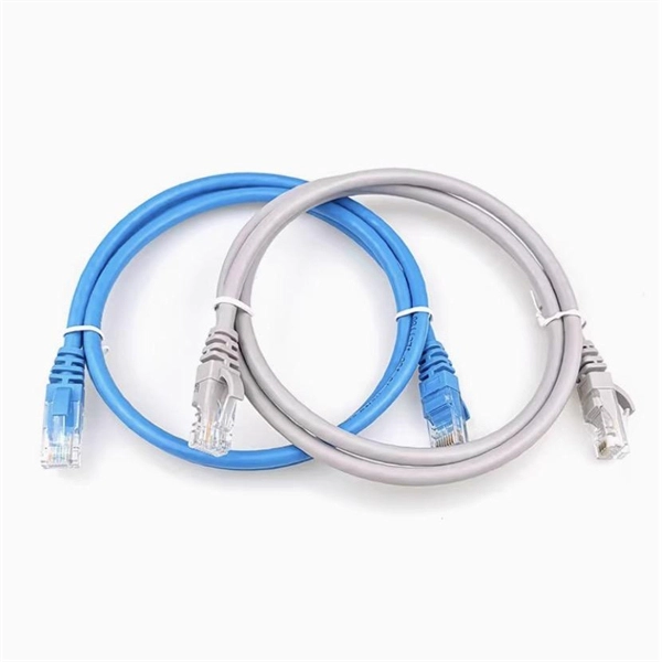
This article provides a detailed technical comparison between fiber optic and copper cables, offering a clear perspective for engineers, network architects, and procurement managers. The core distinction between the two technologies lies in the physics of data. There are significant differences in performance between ADSS cables (all-dielectric self-supporting optical cables) and traditional optical cables, which are mainly reflected in the following aspects: 1. This type of fiber optic cable is designed to support its own weight without the need for additional support structures like messenger wires. The ADSS. There are several factors to assess when deciding which cable type is right for your application, including speed of connection for new customers, ease of changes and repairs, installer certification requirements, and the ability to expand the network over time. ADSS Fiber Optic Cables are a type of optical fiber cable designed specifically for. All-dielectric self-supporting (ADSS) cable is a type of optical fiber cable that is strong enough to support itself between structures without using conductive metal elements. It is used by electrical utility companies as a communications medium, installed along existing overhead transmission.
[PDF]

An Optical Splitter, also known as a beam splitter, is a passive optical device that divides a single input optical signal into two or more output signals. Conversely, it can also combine multiple signals into one. Knowing the difference between a splitter and an optical coupler helps you build better networks. You make your network work better when you pick the right device for each job. You can connect many users to one port with 1:n or 2:n splitters. By dividing a single optical signal from a central Optical Line Terminal (OLT) into multiple outputs for Optical Network Terminals (ONTs) at users' homes, splitters eliminate the need for dedicated fibers to each residence—slashing infrastructure costs while scaling network reach. This guide. In a Passive Optical Network (PON), a single optical fiber carries massive amounts of data using light. Signal Input: The fiber splitter receives the optical signal from the upstream network node and enters the splitter through the input fiber. Signal Distribution: Inside the splitter, according to the design structure and different. Splitters are passive optical devices that divide or combine optical signals, and they come in various types, including power splitters, uneven splitters, and wavelength-division multiplexing (WDM) splitters. Each type serves specific applications, enabling efficient use of optical infrastructure.
[PDF]

This report covers the optical, environmental, and mechanical performance of the LC-UPC, singlemode fiber optic BOAs, provided by Tyco Electronics, Fiber Optics Business Unit. Qualification testing was completed by a third party in July 2004. IDEAL FOR DEBUGGING OPTICAL POWER PERFORMANCE & OPTICAL INSTRUMENT CALIBRATION CORRECION & FIBER SIGNAL ATTENUATION. As optical passive devices, FS attenuators are mainly used in fiber optic to debug optical power performance & optical instrument calibration correction & fiber signal. L-com offers an extensive line of dual wavelength (1310/1550nm) Singlemode fiber optic attenuators. These versatile in-line attenuators are the perfect solution for attenuating Singlemode fiber connectors for both lab and commercial applications. Constructed of the highest quality materials and. zation system's perfo. the power of an optical signal. Our LC/APC single mode attenuators can handle a maximum o 1 watt of optical input power. This device contains one ale and one female LC/APC port. LC/APC optical attenuators can be ordered in attenuation. Fixed loopback type attenuators from OMC offer defined control of optical signals in both integrated and add-on products. Depending on the project or need, fixed attenuators can limit (attenuate) the amount of light passing through to the exact levels your project or application requirement.
[PDF]

This practical file details experiments conducted in Optical Fiber Communication, covering modulation techniques, system components, and performance analysis. An optical fiber is a glass or plastic fiber designed to guide light along its length, widely used in fiber-optic communication, which permits transmission over longer distances and at higher data rates than other forms of communications. Fiber-optic communication is a method of transmitting. Availability of plastic optical fiber (POF) The plastic optical fiber used in some of these experiments is available for science distributors. It is a 1000micron (1mm) POF available from several suppliers. FOA has samples available at no cost for teachers at schools in the US. Key experiments include amplitude modulation, frequency modulation, and pulse width modulation, aimed at understanding fiber optic systems. This document summarizes 10 experiments on optical fiber communication: 1. Studying a 650mm fiber optic analog link and the relationship between input and received signals. Optical fiber communication Laboratory Optical fiber communication Laboratory List of Experiments: 1. To set up a analog optical fiber link 2. To measure the characteristics of LED and LASER 5. Tech curriculum designed to provide a comprehensive understanding of optical fiber communication systems. This lab offers an immersive, web-based simulator that enables you to explore and experiment with key concepts in optical.
[PDF]

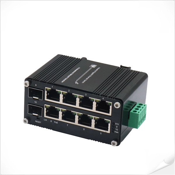
FS optical line protection switch features 1+1 backup and less than 15 ms fast switch to the standby fiber link that ensures business uninterrupted when malfunction occurs. An optical protection switch is a critical component in fiber optic communication systems designed to safeguard optical signals and infrastructure from damage due to power surges, signal overloads, or system failures. These switches ensure signal integrity, minimize downtime, and enhance network. 1+1 Optical Line Protection System for Fiber Protection, Bi-directional Protection in Dual Fiber, LC/UPC, Pluggable Module OLP (Optical Line Protection) is a device used in pairs, one at each end of the optical signal to protect network transmission line. OLP products include fiber optical line protection switches, optical bypass switches, optical cross connection, multi-channel. The FOSW-1x1 or 1x2 optical switch is based on opto-mechanical technology with proven reliability. OSW-W1x2 optical switch is a high performance electro-optical device, with low insertion loss (typic. In optical communication network, OLP monitors optical power of optical fiber and standby.
[PDF]
Here at AFL we provide years of experience and excellent solutions for your hardware needs in both ADSS (All-Dielectric Self Supporting), OPGW (Optical Ground Wire) and SkyWrap cables. Please follow the links below for assistance in choosing your hardware. The aluminum Opti-LoopTM FOS for All Dielectric Self Support (ADSS) cable is available in 3 sizes. With more than one million units in service, Opti-Loop fiber storage systems lead the industry in quality and durability. All aluminum construction with continuous welds at crossbars and ends. Each. Also see our line of ADSS Fiber Optic Cable. © Copyright 2026 AFL. Our product experts are here to assist you. Get in touch with our team now. PLP transmission, distribution, substation, fiber optic, solar, and EV solutions protect and connect overhead electric power lines and communications networks. ADSS Anchor Tension Clamps are hardware fittings used to securely terminate and anchor ADSS fiber optic cables on poles or towers without damaging the cable. This is a type of self-supporting optical fiber cable that does not require any kind of support in distributing electricity from one point to another. As much as they may be independent, these cables are usually installed on poles and.
[PDF]

However, there are still some scenarios where an optical drive is necessary or desirable. What is an Optical Drive?. THe Optical memory is an electronic storage medium that uses a laser beam to store and retrieve digital (binary) data. In optical storage technology, a laser beam encodes digital data on an optical disc or laser disc in the form of tiny pits arranged in a spiral pattern on the surface of the disc. In this article, we'll explore the pros and cons of having an optical drive and help you decide whether you need one. Although a number of optical formats have been used over time, the most common examples are optical discs such as the compact disc (CD) and the digital versatile disc (DVD). The primary components of an optical drive include a laser, a lens system, a motor for spinning the disc, and a decoder to interpret the data. It is commonly found in computers, laptops, and gaming consoles. Optical drives are essential for installing software, playing movies, and backing up data.
[PDF]

NPO (Near-Packaged Optics) is a transitional technology bridging traditional pluggable modules and CPO. It integrates the optical engine and GPU chip side-by-side on the same high-performance PCB or organic substrate, connected via ultra-short high-speed circuits. Its core concept is to remove digital processing units such as DSPs and CDRs from the module, constructing a purely analog "linear direct-drive" optical link. In the LPO architecture: The transmitter uses a high-linearity driver chip to directly drive the optical modulator, converting the. Near-packaged optics (NPO) helps send data faster. It puts the optical engine close to the switching chip. This makes things work better. NPO lets you upgrade easily. You do not have to redesign your whole system. It lowers energy costs. Among the emerging technologies, LPO (Linear Pluggable Optics), NPO (Near-Packaged Optics), and CPO (Co-Packaged Optics) represent three important stages in the evolution of next-generation data center optical networking. Understanding how these architectures differ is essential for designing. Traditional optical modules typically rely on DSPs (Digital Signal Processors) to handle signal equalization, retiming, and compensation, mitigating attenuation and distortion during transmission. They are not concepts at the same level, but rather.
[PDF]

On June 4, 2025, Chile's government and Google formalized an agreement to build the Humboldt Cable, a submarine fiber-optic line that will directly connect South America and the Asia-Pacific region. As of 2025, the plan is to build a 14,800-kilometre (9,200 mi) cable from Valparaiso, Chile, to. But what is complicated is the country being mired in a geopolitical crossfire between Japan and China Telecom in Chile has come a long way since its privatisation in 1980—having the most sophisticated and well-developed infrastructure in Latin America. In 2020, the Chilean government announced a plan to construct a subsea cable to connect Chile and Asia, followed two years later with an announcement to study the feasibility of a subsea cable between Chile and Antarctica. These projects offer opportunities to U. suppliers of fiberoptic and other. Chilean President Gabriel Borich delivered a speech on the construction of submarine fiber optic cable at the Asia-Pacific Economic Cooperation (APEC) CEO Summit on November 15, 2023, in San Francisco, California. Southeast Asia Japan Cable (SJC) 4. This project, first outlined in 2016 and developed through public-private partnership, will run.
[PDF]

Here's a step-by-step guide to help you set up your fiber distribution box seamlessly: Before installing the fiber distribution box, ensure that your optical cables are properly prepared for connection. The optical fiber distribution box allows people to easily access the optical fibers in the box, and can well protect the optical fibers. In addition, the drawer structure also facilitates high-density wiring and good cable management. However, because optical fibers are fragile and can be easily. Keeping this page as a placeholder for now. Have any questions? Talk with us directly using LiveChat. Fix the rack to the ground with expansion bolts. Top installation: Dimensions of four connection holes on the top according to the. This instruction describes the installation of the Fiber Distribution Frame (FDF) manufactured by Corning Optical Communications. To order accessories that are purchased separately, contact Corning Optical Communications customer care for assistance. Read and understand this procedure (as well as. Optical fiber distribution frame is the wiring connection equipment between optical cable and optical communication equipment or between optical communication equipment. Distribution boxes are especially essential for FTTH networks, where they enable the efficient connection and management of optical fibers from a central.
[PDF]
The Intellinet Network Solutions 10 Gigabit Fiber SFP+ Optical Transceiver Module (model 507479) is fully hot-pluggable, and that allows you to install the module without rebooting your network switch for uninterrupted network traffic. Intellinet Network Solutions 10GBase-LR Fiber SFP+ Optical Transceiver Module, model 507479, is the right choice when it comes to connecting two buildings at 10 GbE speeds with single mode fiber. That's a 10 Gbps connection up to a distance of 10 km (or 6.2 miles). The transceiver comes in a mini-GBIC form factor, making it ideal for environments that require many fiber connections by taking up less space in your cabinet and/or computer room. Compatibility in your network is everything, and the Intellinet Network Solutions SFP+ Transceiver Module (model 507479) delivers. Use it with any Intellinet Network Solutions SFP+ equipped network switch or any other MSA compliant SFP+ enabled switch. And since the Intellinet Network Solutions SFP+ transceiver module is set to broadcast the vendor. The Intellinet Network Solutions 10 Gigabit Fiber SFP+ Optical Transceiver Module (model 507479) supports standard digital diagnostics monitoring (DDM) functions, also known as digital optical monitoring (DOM). This gives the user the ability to monitor parameters of the SFP, such as optical output power, optical input power, temperature, laser bia.
[PDF]
An optical time-domain reflectometer (OTDR) is an optoelectronic instrument used to characterize an optical fiber. It is the optical equivalent of an electronic time domain reflectometer which measures the impedance of the cable or transmission line under test. An OTDR injects a series of optical pulses into the fiber under test and extracts, from the same end of the fiber, light that is scatter. Reliability and quality of OTDR equipmentThe reliability and quality of an OTDR is based on its accuracy, measurement range, ability to resolve and. The common types of OTDR-like test equipment are: 1. Full-feature OTDR: 2. Hand-held OTDR and Fiber break locator: 3. RTU in RFTSs:. In the late 1990s, OTDR industry representatives and the OTDR user community developed a unique data format to store and analyze OTDR fiber data. This data was based on the specifications in GR-196, G.
[PDF]
Please select a category, brand, and model to find a type-approved device. Results will be displayed here after search. You can now apply and manage your RSB services online. Start today! The RSB Standards Store has a wide range of Standards covering various sectors and industries. Need help with any of your other applications? Apply for Zamukana Ubuziranenge and get assistance from our staff. Increase the. An LPO (Linear Pluggable Optics) solution offers considerable power savings for optical interconnect by removing the digital signal processing (DSP) function from the pluggable optical module. The idea is simple: instead of a DSP (digital signal processor) inside the module – replacing it with transimpedance amplifier (TIA) and a driver chip with high linearity and EQ capability – LPO shifts signal processing into. LPO (Linear-drive Pluggable Optics) is a transceiver packaging technology. It utilizes specialized components, including ASIC substrates, ASIC. In response, several solutions such as Linear Receive Optics (LRO), Linear Pluggable Optics (LPO) and Co-Packaged Optics (CPO) have been proposed. 1 shows the typical block diagram of a pluggable transceiver consisting of on-board lasers, optics, a Photonics die housing the modulator.
[PDF]
