BSLI is an original equipment manufacturer (OEM) of custom electrical power distribution products. BSLI guarantees its customers fast, personalized service, quality components, and custom-designed equi.
[PDF]

This section provides an overview for optical power meters as well as their applications and principles. Our list of suppliers for that category contains 69 suppliers. Understand the Technical Background To support your technical evaluation, this section includes links to authoritative encyclopedia articles for in-depth verification of the underlying physics, technical issues and techniques. Market Forecast By Type (Thermal Detectors, Photo Detectors), By Instrument/Product Type (Benchtop Meter, Portable Meter, Virtual Meter, Optical Wavelength, Hand-Held Meter, Others), By Detector Type (InGaAs (Indium Gallium Arsenide), Germanium, Silicon, Others), By Power Range (High, Medium, Low). This section provides an overview for optical power meters as well as their applications and principles. Here are the top-ranked optical power meter companies as of May, 2026: 1. Novanta. Photon Systems, Inc. designs, develops, manufactures and markets deep ultraviolet lasers and incoherent sources, instruments based on these sources, and optical and electro-optical accessories for a broad range of applications primarily within the. All of EXFO's modular (IQS line) and benchtop power meters are built for top performance and pinpoint accuracy, and the various models offer a mixture of features and specifications to suit various test setups. Fast, accurate, flexible power. © Copyright© Santec Holdings Corporation.
[PDF]
From the transformer, power goes to the busbar that can split the distribution power off in multiple directions. The bus distributes power to distribution lines, which fan out to customers.OverviewElectric power distribution is the final stage in the. Electricity is carried from the to individual consumers. Distribution connect to the transmission system an. Electric power distribution become necessary only in the 1880s, when electricity started being generated at. Until then, electricity was usually generated where it was used. The first power-distri. Electric power begins at a generating station, where the potential difference can be as high as 33,000 volts. AC is usually used. Users of large amounts of DC power such as some,. Primary distribution voltages range from 4 kV to 35 kV phase-to-phase (2.4 kV to 20 kV phase-to-neutral) Only large consumers are fed directly from distribution voltages; most utility customers are connected to a transformer.
[PDF]
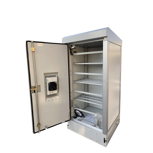
Papua New Guinea's rugged terrain and growing energy demands make outdoor energy storage cabinets a critical component for reliable power distribution. This article explores the unique requirements, technological advancements, and trusted manufacturers serving this dynamic market. This article explores how customized lithium battery systems address remote electrification, mining operations, and renewable integration while boosting sustainability. However, high temperatures and humidity pose challenges for battery longevity. This is where liquid cooling plate technology becomes. Summary: Papua New Guinea's growing energy demands require tailored battery storage systems to support renewable integration, rural electrification, and industrial growth. This article explores how customized energy storage solutions address local challenges, backed by case studies and industry. The project encompasses the construction of a solar and battery energy storage system (BESS) minigrid to be built on the island of Buka, within the Bougainville region. It will address the electricity needs of the region, which relies heavily on diesel generators. The deadline for applications is. Designed for remote locations, it integrates solar controllers, inverters, and lithium battery packs to ensure stable and continuous power for telecom equipment, surveillance systems, and off. Design engineers or buyers might want to check out various Lithium Battery Storage Cabinet factory &.
[PDF]
We are a one-stop shop for top-notch Electrical Cable Tray in Brazil. Our cable trays are manufactured from robust materials and rigorously tested to ensure they can withstand even the most demanding environments. With 8,500 m² of built area, Eletropoll Trays offers to the market electrical ducts, profiles, beds, accessories, fasteners and support, busbars for lighting and related products. The Tray Unit has achieved excellent certifications. We, one of the top Electrical Cable Tray Manufacturers in Brazil, offer a wide. If you are searching for Cable Tray in Brazil, Brilltech Engineers Pvt. is a trusted brand that you can rely on. We have a well-equipped manufacturing unit with all the advanced resources to cater to your distinct requirements as per your industry preferences. Moreover, our focus on maintaining high quality and. EAE Electric started the production and use of busbar trunking systems in Turkey in the 1970s. Support systems can be manufactured with thicknesses from 2mm to 6mm with Pre-galvanized, Hot Dipped Galvanized, and Painted coatings in various options. EAE cable trays are produced on automatic. Chalfant Ladder Cable Tray Systems are ideal for indoor and outdoor cable management. They provide reliability, ease of installation, and cost savings both initially and long term. With multiple finishes available, we have the perfect ladder tray for any environment. screwless connections.
[PDF]
In 1880, and his assistant created a very early precursor to fiber-optic communications, the, at Bell's newly established in. Bell considered it his most important invention. The device allowed for the of sound on a beam of light. On June 3, 1880, Bell conducted the world's first wireless transmission between two buildings, some 213 meters apart. Due to its use of an atmospher.
[PDF]

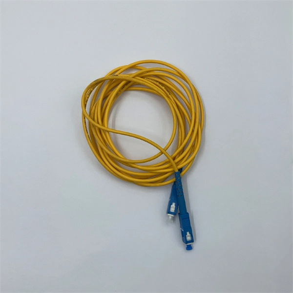
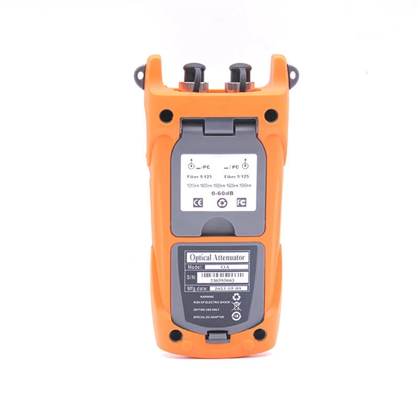
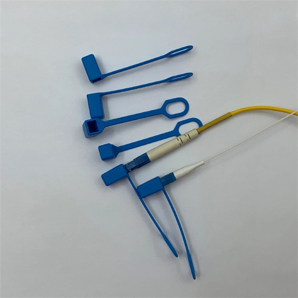
To use a power meter for fiber optic testing, always clean connectors first with lint-free wipes or click-to-clean tools. Select the correct wavelength and set your reference. You measure optical power in dBm or insertion loss in dB. Consistent procedures ensure accuracy. Verify light travels from. The most basic fiber optic measurement is optical power from the end of a fiber. This measurement is the basis for loss measurements as well as the power from a source or presented at a receiver. Typically both transmitters and receivers have receptacles for fiber optic connectors, so measuring the. An optical power meter measures the strength of light traveling through a fiber optic cable, giving you a reading in dBm (decibels relative to one milliwatt). This article will guide you through the methods, instruments, and key considerations for measuring fiber. Fiber optic cabling is the high-performance core of today's datacom networks. As network speeds and bandwidth demands increase, fiber performance requirements have become more stringent. Fiber testing is more important than ever. An OPM uses a photodiode to generate an electrical current proportional to optical power.
[PDF]
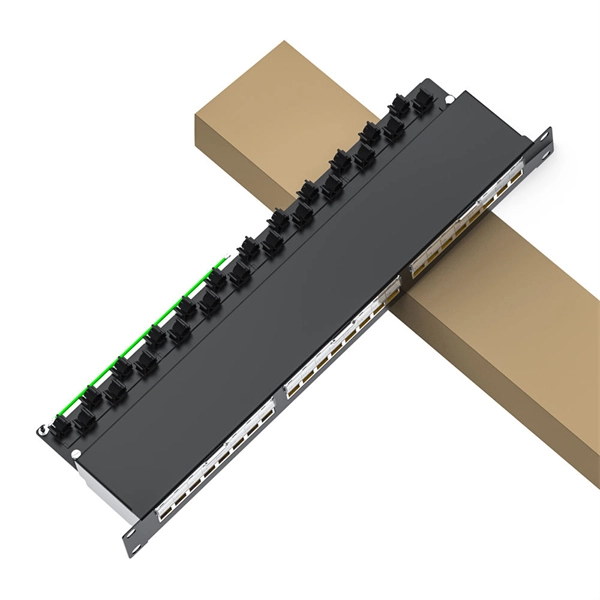
Quality Libya power strips, in stock, for standard duty applications up to industrial applications. Versions designed for PDU power distribution purposes in data centers and server room applications. As Data Centers evolve to handle increasing power densities driven by AI, cloud computing, and high-performance applications, PDUs have advanced from simple power strips to intelligent systems offe ing Monitoring, Remote Management, and. Voltz engineers high-performance power distribution solutions for mission-critical infrastructure. Integrated protection. UL-891 and ISO 9001:2015 compliant. The space-saving PDU is easy to move and adapt to the future demands of the data center. The PDU offers superior power protection and monitoring, and the flexibility. From basic PDUs, to monitored and switched rack power distribution units, to locking receptacles, Vertiv's solutions will offer the power distribution you need, as well as remote monitoring and management of your assets' power usage, so you can rest assured everything is running at peak. Hyper Power Distribution Units (PDUs) are engineered to redefine efficiency, flexibility, and reliability in mission-critical environments. Designed for the most demanding applications, our PDUs support transformer capacities ranging from 300 kVA to 2,000 kVA, providing scalable solutions for.
[PDF]

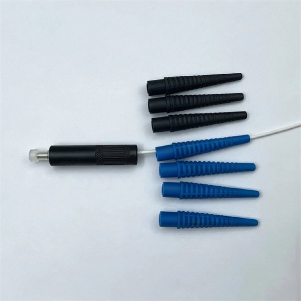
Select the correct wavelength and set your reference. You measure optical power in dBm or insertion loss in dB. Consistent procedures ensure accuracy. Measure total signal loss from fiber, connectors, or splices. Optical fiber attenuation is the attenuation per unit length of optical fiber, and the unit is dB/km. When connecting two optical fibers, there will be loss inside any connector or joint. Consistent measurement techniques. While optical power meters are the primary power measurement instrument, optical loss test sets (OLTSs) and optical time domain reflectometers (OTDRs) also measure power in testing loss. TIA standard test FOTP-95 covers the measurement of optical power. Optical power is based on the heating power. Light Source: The CMA5 Series Light Sources provide an economical and stable laser source for use in point-to-point attenuation measurement. They feature a rugged design, built to withstand the difficult testing environment of fiber optic cable installation and maintenance. The CMA5 Light Sources. When talking about optical measurements, wavelength basically means how far a wave pattern repeats itself, usually measured in nanometers (nm). Commonly, a power meter on its own is used to measure absolute.
[PDF]
Whether you're building a commercial setup or upgrading an industrial plant, proper cable tray installation ensures neat wiring, safe access, and easy maintenance. But before you lay the first tray or clamp down a single cable, you need a solid plan. This guide breaks. This method statement covers the site installation of the cable tray & ladders and the requirements of checks to be carried out. The Cable Tray system is installed in electrical rooms, plant rooms, and service corridors. This guide breaks down the process step by step. This process is integral to determining the optimal arrangement and configuration of cable trays, which are essential for routing and supporting electrical cables within buildings and. 1. 0 This method statement will serve as a minimum guideline to carry out the Cable Tray Installation activities for commercial buildings, plants and refineries in accordance with Project Drawings and Specifications. This document outlines the key requirements for cable tray layout, installation, and fireproofing in industrial and commercial environments. Route. Below is the detailed cable tray installation method statement not only for cable tray but also applicable for GI ladder and trunking for indoor and outdoor applications and in service rooms like pump rooms, electrical rooms and plant rooms etc. All materials intended for cable tray, ladder and.
[PDF]
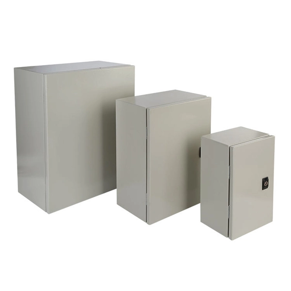
Incoming power wires must use conduit connections on the bottom plate of the MCC structure to enter the ArcBlok-equipped main circuit breaker unit. A distribution box is the heart of any electrical system. Whether in a home or an industrial facility, this box keeps your electrical setup organized, functional, and efficient. However, the key to. Start by shutting off power at the main disconnect to prevent shock hazards. Remove the panel cover to access internal conductors. Line terminals, typically located at the top of the enclosure, receive incoming service from the utility. These are usually connected to thick black or red wires, each. These boxes full of circuit breakers or fuses distribute incoming power to wiring circuits throughout the house. Top-feed MCC main circuit breaker units with ArcBlok 1200 include a required, 18 in. Commercial line box: Designed for commercial facilities such as office buildings and shopping malls, it has a larger carrying capacity and.
[PDF]

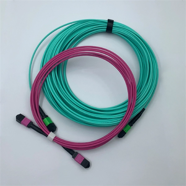
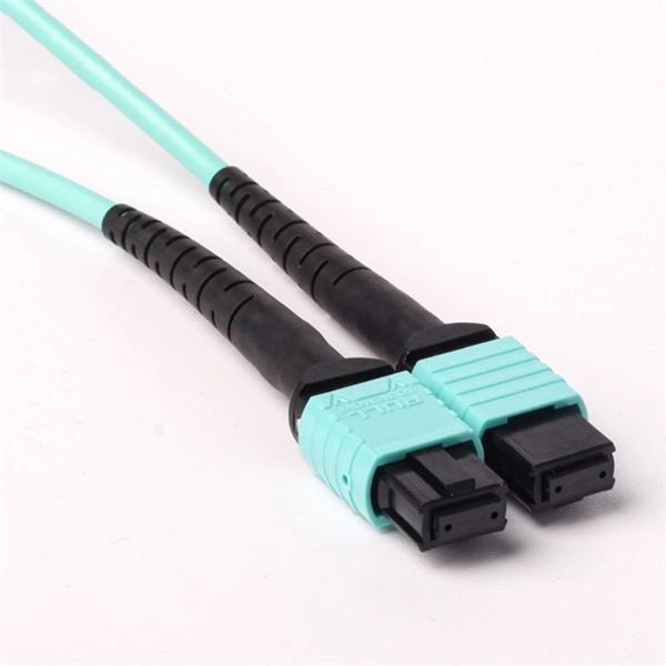
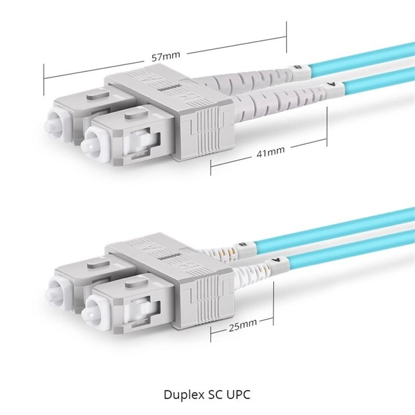
This article will introduce passive optical networks (PON), in which we will introduce everything about OLTs, ONTs, ONUs, and ODNs, including their operation principles and functions. PON (Passive Optical Network) refers to a fiber optic network built using a point-to-multipoint topology and fiber. Active Optical Networks (AON) and Passive Optical Networks (PON) make FTTH broadband connections possible. To date, most FTTH deployments in planning and deployment have used PON to save on fiber costs. PON has attracted much attention in recent years due to its low cost and high performance. There are no specific requirements for this document. This document is not restricted to specific software and hardware versions. The information in this document was created from the devices in a. OLT, ONU, ONT, and ODN are key components and acronyms used in Passive Optical Network (PON) architecture, which is a popular technology for delivering high-speed broadband services. This technology is widely used in fiber-to-the-home (FTTH) and fiber-to-the-premises (FTTP) deployments. In contrast to AON, multiple customers are connected to a single transceiver by means of. An Optical Distribution Network (ODN) serves as the bridge in a Passive Optical Network (PON), transmitting optical signals from the Optical Line Terminal (OLT) to the Optical Network Unit or Terminal (ONU/ONT), thus linking a service provider's core network to end-users (residential or business).
[PDF]
A neat, well-organized subpanel bundles wires to conserve space and improve access. Ideally, wire groups are installed in layers and wires are bent at right angles to buses or breakers. Label short sheathing sections (slugs) to indicate which circuits wires serve. We cover everything from separating color-coded wires and securing them with ties to. Discover 7 DIY tips to organize your electrical panel for improved safety, easier troubleshooting, and efficient maintenance. Prevent hazards while making your home's electrical system more manageable. A disorganized electrical panel isn't just an eyesore—it's a safety hazard and troubleshooting. According to NEC (National Electric Code: Article 1 00-Definitions), a Main Panel (also known as Panelboard, load center, breaker box and distribution board etc. ) is a cabinet or cutout box which contains on controlling and protective devices (such as circuit breakers, fuses, switches etc. ) used to. Welcome to this live training session! ⚡ In today's tutorial, I'll be demonstrating how to arrange cables neatly inside a distribution bo. more See what others said about this video while it was live. If you're struggling with unsightly cords hanging around your cabinets, worry not! In this guide, we'll explore practical strategies to conceal those wires effectively. Before starting the process of.
[PDF]
This video shows real on-site footage of electrical installation, demonstrating safe and standardized wiring methods used by professionals. An electrical distribution box, also known as a power distribution box, panelboard, or consumer unit, is the core of an electrical system. It has three categories: residential, commercial and industrial electrical distribution boxes, all of which play important roles in their respective electrical. Learn how to install a distribution box safely and correctly. Covers wiring, placement, standards, and expert tips for a compliant setup. It takes the incoming power and safely distributes it to different circuits throughout your building. more Learn how to wire a distribution box step by step! This video shows real on-site footage of. A distribution board or distribution box is where the main power supply is distributed to multiple loads. And all the switching and protective devices are installed in the distribution box. Single Phase Distribution Box generally consists of Double Pole MCBs, Single Pole MCBs, and RCCBs. Unlike single-phase systems, where power is distributed using. Phase 3's Powersafe Sequential Mating Box controls the connection sequence of incoming / outgoing high current cable connections. The sequence ensures that the Earth connection is made first and disconnected last. (FMLB- First Mate Last Break). With key (included) turn the Earth lock clockwise (Fig.
[PDF]
Electric power distribution systems are designed to serve their customers with reliable and high-quality power. The most common distribution system consists of simple radial circuits (feeders) that can be ove.
[PDF]