In this beginner-friendly guide, we'll explain what it is, why the “APC” matters, the different types you can buy, how to select the right model, and how to install and test it correctly. What is an SC/APC Fiber Optic Adapter?. Fiber optic adapters, also known as couplers, play a crucial role in fiber optic networks by providing a connection point between two fiber optic connectors. They enable seamless and reliable optical signal transmission between different fiber optic cables, connectors, or devices. Using the wrong type or neglecting cleaning can lead to signal loss and unstable connections. This guide covers adapter types, selection criteria, cleaning tips, FAQs, and B2B customization options to help businesses build reliable and scalable fiber networks. It ensures precise alignment between fibers and facilitates effective transmission of optical signals. Without the proper adapter, signals can degrade or become unstable, which can dramatically decrease the reliability of a network.
[PDF]
Here, our research reports a spatial–temporal hot spot management system integrated with fiber Bragg grating (FBG) temperature sensor arrays and cooling hydrogels. MEISU's high temperature resistant fiber array is assembled with fibers of special high-temperature coating and special epoxy, thus to ensure the whole assembly can survive 260°C and capable of going through reflow oven. High temperature resistant fiber array's structure is actually the same with. In particular, the hot spot effect plays a vital role in weakening the power generation performance and reduces the lifetime of photovoltaic (PV) modules. HT (260℃)Fiber Array Feature Fiber count: 1, 2, 4, 8, 12, 24, 32. Abstract: Ultra-weak fiber Bragg grating (UWFBG) arrays are key elements for constructing large-scale quasi-distributed sensing networks for structural health monitoring. Conventional methods for creating UWFBG arrays are based on in-line UV exposure during fiber drawing. However, the UV-induced. To enhance the high-temperature performance of the fiber Bragg grating array (FBGA), an on-line writing high-temperature resistant FBGA is proposed. FBGA is coated with polyimide and is written on the drawing tower by single laser pulse with phase mask technology. After continuous processes of.
[PDF]

Communication networks are an integral part of interconnected transmission lines in a power grid, analogous to the spinal cord for control signal and information exchange among substations, data hubs, and load dispatch centers. This article cov. Communication networks are an integral part of interconnected transmission lines in a power grid, analogous to the spinal cord for control signal and information exchange among substations, data hubs, and load dispatch centers. This article covers the major trend and design aspects of fiber optics communication link in power transmission line netwo. The communication network in the power grid is one of the most interrelated systems that require perfect compliance in equipment and protocol selection. While the high voltage components are relatively unchanged over decades in terms of operating principles, the communication protocols and equipment are seeing astonishing advancements every year. S. 2.1 Knowhow of prevailing setupWhile the primary objective is always to get the best solution for the lowest price, in the case of extension projects, the design engineers must also keep an eye on the existing setup. The issue of back-compatibility and upgradationsshould be properly accessed in existing equipment, even more so in the case of proprietary legacy setups. Figure below illustrates one such group of communication equipment in existing substations that might need proper interfacing and compatibility adapters befo.
[PDF]

Optical fibers or fiber cables can be used for transmitting optical power from a source to some application. In their served areas will be power generating stations, alternative energy sources (solar, wind, geotherman, etc. ), substations for distribution and microgrids. These networks must be monitored and managed to ensure reliable power for the utility's customers. For monitoring and managing networks. Low voltage cables are mounted on poles in the "telecom space," well below power cables. Optical power ground wire (OPGW) is an electrical power ground with fiber optics in the center of the conductor. That conversion can be done with a photovoltaic cell. The Commission, on June 22, 1965, noting that the increasing demand for underground electric and communication facilities in California has brought about substantial increases in the construction of such facilities, and that it appeared it may be desirable, pursuant to Sections 761, 768 and 8056 of. One choice is optical power ground wire (OPGW). This conductive cable is run at the top of the tower or pole to be the ground conductor and protect the power cables from lightning. The fiber. While fiber optics is essential for internet service providers to deliver higher bandwidth and faster transmit speeds, there are also many crucial benefits of fiber optics in energy and power. Utility companies face various challenges as they work to deliver reliable energy to homes and industries.
[PDF]

In this video im showing and explaining how to climb a power pole using a fall protection belt, also drilling into a pole and framing it for 1/4 strand that will supports the fiber optic cable. more. Deploying fiber above ground on poles or towers removes the need for underground digging and is particularly useful when the ground is uneven, rocky or both. Aerial installation is generally much less costly than underground construction also. Fiber in a duct solutions have a major aesthetic. The Fiber Optic Association, Inc. (FOA) was founded in 1995 to help develop the workforce to build the fiber optic networks to support a rapid expansion in communications and the Internet. This lesson covers the installation of poles and. ADSS (All Dielectric Self Supported fibre optic cables) OPGW (Optical Ground Wire) The installation methods for fibre optic cables are largely the same as those with conventional copper cables. These may be considerably different from those of the copper cable. When installed correctly, ADSS cables can last more than 25 years, providing stable, high-speed communication even in difficult outdoor environments. But to get the best.
[PDF]

Instead of relying on assumptions, this guide offers a clear-eyed look at how to properly secure your fiber infrastructure, moving beyond the myths to implement practical, layered defenses that provide real-world protection for your organization's most sensitive data. For manufacturers and industry professionals involved in creating, deploying, or maintaining these critical systems, ensuring the robust and reliable securement of fiber optic cables is paramount. “Securing” fiber optic cable goes beyond just preventing it from moving; it encompasses protecting its. Fiber optic cables enable high-speed, long-distance data transfer, forming the backbone of modern communication. Yet, outdoors, they face temperature swings, moisture, UV exposure, rodents, and human interference. Protecting them is essential for long-term reliability. This guide covers how to. Fiber optic and ACSR (Aluminum Conductor Steel Reinforced) cables play a critical role in modern infrastructure, including power transmission and telecommunications. However, these cables face several challenges that can compromise their performance and longevity. If you are an optical engineer or a fiber optic network operator, you need to know how to protect your cables from these threats and ensure. An effective fiber optic network security plan acknowledges these potential weak spots and addresses them head-on. Before beginning any installation, safety.
[PDF]

Fiber optic transmission distance varies based on fiber type, environmental conditions, and equipment selection. This guide explores the key factors affecting fiber optic transmission distance and provides practical selection guidelines for a stable and cost-effective network. Receiver Sensitivity Higher receiver sensitivity means that it can detect weaker optical signals. Even if the optical signal power is low, the receiver can still detect and decode the signal correctly, extending the transmission distance of fiber optic communication. Another consideration is that. Fiber optic cable transmission distance is determined by two primary physical factors that affect signal quality as light travels through the fiber medium. For most enterprise or data center applications using multimode fiber, the practical limit sits between 300 m and 550 m. Single-mode. Estimate one-way and round-trip timing for fiber runs, optics, and active hops in home labs and backbone links. Direct point-to-point links with OS2 single-mode 1310 nm typically use 10 km+ of practical reach. Configuration type Fiber profile Route length Measured in feet for imperial mode. Apply a waste factor based on site practice. Click Calculate to see totals and the breakdown. Use the export buttons to share results. For critical links, verify on drawings and allow extra for rework. Fiber length takeoff starts with a measured route. Break the pathway into segments for tray runs.
[PDF]

Fiber optic connector pull test demonstration with real-time insertion loss monitoring. We use an optical loss tester to track signal stability every second while controlled tension is applied to the fiber. more. Fiber optic cable is surprisingly strong, durable and pliable; however, several best practices should be followed to ensure a successful cable installation. The below article explores the best practices and tools commonly used to pull fiber optic cable. The Future Ready Solutions Tools & Test. NEOFIBO TFTM-100N Vertical Fiber Optics Cable Tension Testing Machine The Cable Tensile Testing Machine is a precision mechanical measuring instrument designed to evaluate the tensile strength and elongation properties of various cables, wires, and fiber optic assemblies. Most fiber damage does not come from normal operation after the system is live. It happens during installation, when excessive pulling force, tight bends. Fiber optic connectors are designed to be connected and disconnected many times without affecting the optical performance of the fiber circuit. Optimal performance can be achieved by following the correct process for termination of the fiber circuit—a task which requires the use of a wide range of. The Fluke Networks JR-LEV-1 JackRapid Punch Down Tool is a cable termination tool that is designed to give technicians maximal efficiency in cable maintenance.
[PDF]
The normal recommendation for fiber optic cable is the minimum bend radius under tension during pulling is 20 times the diameter of the cable (d). This includes pulling tension, minimum bend radius or diameter and crush loads. Installers must understand these specifications and know how to install cables without. Fiber optic cable bend radius is a critical mechanical parameter that determines how sharply a cable can be bent without risking microbending, macrobending, signal loss, or long-term structural fatigue. It is measured from the inside of the bend, not the outer curve. Fiber optic cables transmit data through light propagation within a glass core. The correct bend radius calculation is a fundamental prerequisite for high-quality fiber optic installations and is decisive for long-term network performance and reliability. While installers are aware of the fundamental importance of minimum bend radii, they often lack the practical know-how to. The bend radius of fiber cables is critical for maintaining high performance and longevity. This overview explains key standards, installation best practices, and consequences of exceeding limits during handling, routing, and management. What Is Bend Radius? You need to understand the concept.
[PDF]
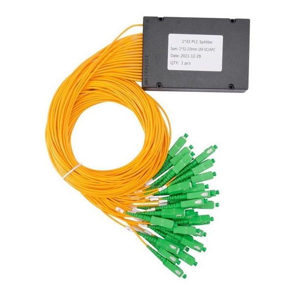
FC-FC Type: Commonly known as circular to circular tail fiber, typically used for jumpers between ODF racks. At the first step of phage infection, the receptor-binding proteins (RBPs) such as tail fibers are responsible for recognizing specific host surface receptors. The proper folding and assembly of tail fibers usually requires a chaperone encoded by the phage genome. Despite extensive studies on phage. Bacteriophage Mu is a temperate phage known to infect various species of Enterobacteria, playing a role in bacterial mutation induction and horizontal gene transfer. This initial binding is a fundamental step that dictates whether a phage can successfully infect a particular bacterial cell. Tail. A tail fiber, also known as a fiber optic patch cord, consists of a connector on one end and a cut end of the fiber optic cable core on the other. These patch cords are primarily used to connect fiber optic cables to fiber optic transceivers (couplers, jumpers, etc.
[PDF]
Shop cable conduit and interduct for fiber and network cable protection. Ideal for both indoor/outdoor use, this product is easy to install. 1" PVDF Plenum Rated Fiber Innerduct Snap Coupling (for F1-11437 and F1-11437S only). Corrugated, smooth or split wall types. Fiber cable tray/duct is designed to protect and route fiber optic patch cords, multi-fiber cable assemblies, and intrafacility fiber cables (IFC) to and from fiber splice enclosures, fiber distribution frames and fiber optic terminal devices. Our fiber duct/tray is manufacturder with fire. Innerduct is used to protect fiber optic cables as they are routed through buildings or underground. Inner duct product line consists of corrugated HDPE, riser rated PVC and plenum rated PVDF. UL 2024 listed and among the most flexible flame-rated Inner duct products on the market. These ducts are essential for maintaining signal integrity, preventing physical damage, and ensuring long-term reliability in various environments. PVC innerduct conduit is non-metallic, lightweight, corrugated, and flexible to protect and route electrical wire and cables. Note: Product availability. 1-1/4" Diameter, Corrugated HDPE (High Density Polythylene) Innerduct, Orange. Includes: Pull String. No UV Protection, not suitable for outdoor use. Category: Corrugated.
[PDF]
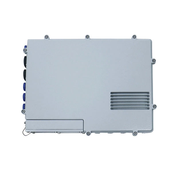
The fiber termination box is an essential component in the realm of fiber optic networks, providing a structured and secure location for splicing, terminating, and managing fiber optic cables. This product not onl.
[PDF]

The procedures in this document describe basic inspection techniques and processes of cleaning for fiber optic cables, bulkheads, and adapters used in fiber optic connections. Note: This document is intended for use by service personnel, field service technicians, and. There are three main principles that needs to be taken in consideration for an efficient optical connection: a perfect core alignment, perfect physical contact and dirt-free connectors. It is important that every fiber connector be inspected and cleaned prior to mating. That advice is misguided. It could hurt an installer or get them sued by an irate network owner. This guide outlines best practices for maintaining and inspecting installed fiber optic infrastructure, enabling network owners to keep their systems running at peak efficiency. Fiber optics infrastructure consists of optical fiber cables, connectors, splice enclosures, distribution panels, and. Small oil micro-deposits and dust particles on fiber optic cable optical surfaces may cause a loss of light or degraded signal power which may ultimately cause intermittent problems in the optical connection. Fiber optic testing and maintenance protocols not only maintain the reliability of the network, but also allow for early detection of potential failures and optimization of performance.
[PDF]

Optical Fiber Communication (OFC) revolutionizes modern telecommunications, enabling rapid data transfer across long distances with minimal signal loss. This comprehensive review explores OFC's historical evolution, core principles, components, and versatile applications. It traces OFC's. Additionally, optical fiber is lightweight and less susceptible to noise (no electromagnetic induction). Optical fiber consists of a cylindrical core that propagates light and a concentric cladding that surrounds it. The cladding's refractive index is slightly smaller than that of the core, which. Fibre optics and optical communications is the use of thin strands of glass for sending information encoded into light over long distances. Total internal reflection prevents light inserted into one end of the fibre from escaping through the sides. Keywords: Optical fibers, communication systems, data. Figure 1: Illustration of the inverse-square law of light intensity – the light's intensity diminishes with the square of the distance, which free-space optical signals must overcome (leading to very weak reception at long range) Figure 1 illustrates how light intensity decreases as distance.
[PDF]

Typical total project ranges and per-meter ranges with assumptions: A straightforward indoor fiber install with standard single-mode cable might cost about $0. 50 per meter for cable alone, with total project costs commonly in the $0. 50 per meter range when including labor. Fiber-optic cable materials typically cost $1 to $6 per linear foot, depending on fiber count and cable type. Commercial building installations with 100-200 network drops generally range from $15,000 to $30,000. Single-mode fiber costs less per foot than multimode fiber, but it requires more. Single-mode fiber (OS2): This is the industry workhorse. In 2025, the base glass price has stabilized. You are looking at $0. The price swing usually depends on the fiber count (e., 12-core vs 96-core) and brand. Generic. Buyers typically pay for fiber optic cable by length, fiber type, and installation complexity. Main cost drivers include cable grade (indoor vs outdoor, armoured), distance, and labor for trenching, splicing, and termination. This guide presents ranges in USD and practical price estimates to help. The unit cost of fiber optic cables can vary from $0. Here's a general pricing reference: Cable TypePrice Range (USD/meter)Simplex / Duplex Indoor Cable$0. 30Single-mode Outdoor Cable$0. 50Multimode (OM1/OM2/OM3)$0. On average, the cost can range from $2.
[PDF]