In short length cables a visual fault locator (VFL) can find where the cut is or find the bad connector at patch panels. For longer distance cables, the use of an OTDR is required. Once the fault is located, fusion splicers and splice-on connectors can be used to complete the repair. Fiber optic cables are the backbone of modern networks, delivering fast and reliable data transmission. Accidental cuts, breaks, or other damage can disrupt your network and cause costly downtime. With the right tools and techniques, you can efficiently repair damaged fiber cables and restore. Fiber optics offers advantages like EMI immunity and low attenuation (0. 2 dB/km), but it's fragile—susceptible to breaks, bends, and contamination. Repairs focus on restoring the light path with minimal signal loss (<0. A fusion. Visual inspection and specialized tools like OTDRs, OPMs, and VFLs are essential for identifying and locating physical damage or faults in fiber optic cables. Emergency restoration planning involves implementing backup power solutions, network redundancy planning, and strategies for prompt. Fiber optic cables are critical components of modern communication networks, transmitting vast amounts of data at lightning speeds.
[PDF]

KPC operates a ninety-six (96No. ) core Fibre Optic Cable (FOC) that runs along the oil pipeline. KPC was licensed by the Communications Authority of Kenya (CAK) in 2018 to offer FOC services to telecommunications firms in the form of dark fiber leases. The government is set to save Ksh 170 billion through a deal between the Kenya Power Company and the Ministry of ICT, utilizing Kenya Power's transmission lines to roll out 100,000 kilometres of fibre optic cable across the country. The Information Communication and Technology Ministry has revealed that the government is set to save billions by using Kenya Power to create an internet connection. In the new deal which was announced by Energy Minister Davis Chirchir, Kenya Power is set to undertake the connection of fibre optic. KPC operates a ninety-six (96No. By utilizing Kenya Power's transmission lines for the rollout of 100,000 kilometers of fibre. Kenya Pipeline Company (KPC) as part of business diversification and to meet their ever-increasing bandwidth demand for voice, data and video, obtained a Network Facility Provider (NFP) - Tier 2 Network Infrastructure License in 2018 from Communications Authority of Kenya (CA) to lease Fiber Optic.
[PDF]

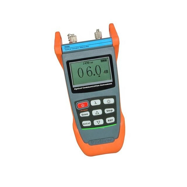
While optical power meters are the primary power measurement instrument, optical loss test sets (OLTSs) and optical time domain reflectometers (OTDRs) also measure power in testing loss. TIA standard test FOTP-95 covers the measurement of optical power. This measurement is the basis for loss measurements as well as the power from a source or presented at a receiver. Typically both transmitters and receivers have receptacles for fiber optic connectors, so measuring the. You need a power meter to measure power in a fiber optic system; most power meters come with a screw-on-adapter that matches the connector being tested and a little aid from the network electronics to turn on the transmitter. During the measurement of power, the meter must be set to the proper. Fluke Networks sets the standard in network testing with its advanced range of fiber optic power meters and fault locators, designed to ensure the highest precision in fiber optic meter readings and power evaluations. This is measured in decibels (dB). Splitters, fusion splices, connectors and. To use a power meter for fiber optic testing, always clean connectors first with lint-free wipes or click-to-clean tools. Select the correct wavelength and set your reference. Consistent procedures ensure accuracy.
[PDF]
A 4 Core Optical Cable is a fiber optic cable that contains four individual optical fibers within a single protective outer jacket. Each fiber is capable of independent data transmission. A TOSLINK optical fiber cable with a clear jacket. These cables are used mainly for digital audio connections between devices. A fiber-optic cable, also known as an optical-fiber cable, is an assembly similar to an electrical cable but containing one or more optical fibers that are used to carry. This guide covers everything you need to know about 4 core fiber, including its internal structure, TIA standard color coding, and how to choose the right type. They are ideal for long-distance communication and. But generally, the cable core, strength member and outer sheath together make a fiber optic cable. It transmits electricity or information from one place to another. These fibers are used to transmit data as light signals, offering high-speed data transfer capabilities over long distances with minimal loss. Fiber optic cables are crucial.
[PDF]

In this beginner-friendly guide, we'll explain what it is, why the “APC” matters, the different types you can buy, how to select the right model, and how to install and test it correctly. What is an SC/APC Fiber Optic Adapter?. Fiber optic adapters, also known as couplers, play a crucial role in fiber optic networks by providing a connection point between two fiber optic connectors. They enable seamless and reliable optical signal transmission between different fiber optic cables, connectors, or devices. Using the wrong type or neglecting cleaning can lead to signal loss and unstable connections. This guide covers adapter types, selection criteria, cleaning tips, FAQs, and B2B customization options to help businesses build reliable and scalable fiber networks. It ensures precise alignment between fibers and facilitates effective transmission of optical signals. Without the proper adapter, signals can degrade or become unstable, which can dramatically decrease the reliability of a network.
[PDF]

Instead of relying on assumptions, this guide offers a clear-eyed look at how to properly secure your fiber infrastructure, moving beyond the myths to implement practical, layered defenses that provide real-world protection for your organization's most sensitive data. For manufacturers and industry professionals involved in creating, deploying, or maintaining these critical systems, ensuring the robust and reliable securement of fiber optic cables is paramount. “Securing” fiber optic cable goes beyond just preventing it from moving; it encompasses protecting its. Fiber optic cables enable high-speed, long-distance data transfer, forming the backbone of modern communication. Yet, outdoors, they face temperature swings, moisture, UV exposure, rodents, and human interference. Protecting them is essential for long-term reliability. This guide covers how to. Fiber optic and ACSR (Aluminum Conductor Steel Reinforced) cables play a critical role in modern infrastructure, including power transmission and telecommunications. However, these cables face several challenges that can compromise their performance and longevity. If you are an optical engineer or a fiber optic network operator, you need to know how to protect your cables from these threats and ensure. An effective fiber optic network security plan acknowledges these potential weak spots and addresses them head-on. Before beginning any installation, safety.
[PDF]

Optical fibers or fiber cables can be used for transmitting optical power from a source to some application. In their served areas will be power generating stations, alternative energy sources (solar, wind, geotherman, etc. ), substations for distribution and microgrids. These networks must be monitored and managed to ensure reliable power for the utility's customers. For monitoring and managing networks. Low voltage cables are mounted on poles in the "telecom space," well below power cables. Optical power ground wire (OPGW) is an electrical power ground with fiber optics in the center of the conductor. That conversion can be done with a photovoltaic cell. The Commission, on June 22, 1965, noting that the increasing demand for underground electric and communication facilities in California has brought about substantial increases in the construction of such facilities, and that it appeared it may be desirable, pursuant to Sections 761, 768 and 8056 of. One choice is optical power ground wire (OPGW). This conductive cable is run at the top of the tower or pole to be the ground conductor and protect the power cables from lightning. The fiber. While fiber optics is essential for internet service providers to deliver higher bandwidth and faster transmit speeds, there are also many crucial benefits of fiber optics in energy and power. Utility companies face various challenges as they work to deliver reliable energy to homes and industries.
[PDF]

The typical specification range of return loss of a fiber connector is -15 dB to -60 dB. Return loss is also known as reflection loss. It indicates the amount of signal reflected back to the transmitting end. Return loss refers to the power loss caused by the reflection of part of the signal back to the signal source during transmission due to the discontinuity of the transmission. Insertion loss, also known as attenuation, is the loss of optical power that occurs when light passes through a fiber optic connector. It is caused by factors such as misalignment, air gaps, and imperfections in the connector components. The lower the insertion loss, the better the performance of. Reflectance (which has also been called "back reflection" or optical return loss) of a connection is the amount of light that is reflected back up the fiber toward the source by light reflections off the interface of the polished end surface of the mated connectors and air. It is also called. Insertion Loss (IL) is the amount of optical power lost as the signal travels from one point to another in a fiber optic link, usually across connectors or splices. Formula for. In optical fiber communication, insertion loss and return loss are two important parameters to evaluate the quality of interfaces between some optical fiber components, such as optical fiber connector, fiber patch cable, pigtail fiber, etc. While it's natural to have.
[PDF]
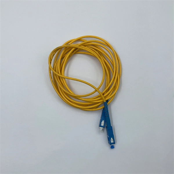
Single mode and multimode fiber optic cables are two different types of fiber optic cable aimed at different use cases. Single mode cables are typically made with a single strand of glass at their core, leading to a n.
[PDF]

This report studies the global Single Mode Fiber Optic Cables production, demand, key manufacturers, and key regions. OPCOM produce wide range of fiber optic cables for multi applications. These cables are designed and engineered to quality performance for industry and end-to-end solutions. This report is a detailed and comprehensive analysis of the world market for Single Mode Fiber Optic Cables, and provides market size (US$ million) and Year-over-Year (YoY) Growth. UnitekFiber produces high quality of MPO|MTP Cables, Fiber Optic Patchcords, SFP Optical Transceivers, MPO|MTP Patch Panels and Outdoor Fiber Cables. We design, create and deliver reliable and cost effective fiber optic products to meet customers' business goals. We have delivered our fiber optic. Optic Digital Fiber Optic Cables | DCD Distribution. Structured Cabling, Fiber Optic, UPS & Power Systems Supply Malaysia. 6 product in this category. A single mode fiber optic cable is a high-performance transmission medium designed to carry light signals over long distances with minimal signal loss. Widely used in telecommunications, data centers, and enterprise networks, these cables are essential for high-speed internet, voice, and video. Our fiber optic cable facility, over 20,000 square meters, boasts more than 35 production lines, managed by around 300 well-trained staff and engineers. Factory direct sales from the fiber optic.
[PDF]
Single mode and multimode fiber optic cables are two different types of fiber optic cable aimed at different use cases. Single mode cables are typically made with a single strand of glass at their core, leading to a n.
[PDF]
This article will guide you through the process of troubleshooting fiber optic connections, with a focus on ensuring proper TX and RX alignment and how to correctly switch patch cables to resolve issues. This document describes how to troubleshoot fiber optic interfaces by addressing some of the fiber optic module and cabling specifications. There are no specific requirements for this document. The information in this document is based on all Catalyst 9000 Series switches. This includes Doppler. Fiber optic networks are celebrated for their speed and reliability, but even the best systems can encounter problems. When issues like signal loss, slow speeds, or intermittent connectivity arise, systematic troubleshooting is key. 8750) Description: Internet address is. There is a single mode optical fiber cable in our datacenter going from a Cisco N5K to another N5K across different racks. The link appears to be dead and I'm hoping to fix it, but I have little to no experience with fiber. The LED light of the SFP+ ports on both switches are off (not lighting up).
[PDF]
Modern fiber-optic communication systems generally include optical transmitters that convert electrical signals into optical signals, to carry the signal, optical amplifiers, and optical receivers to convert the signal back into an electrical signal. The information transmitted is typically generated by computers or.
[PDF]

Fiber optic transmission distance varies based on fiber type, environmental conditions, and equipment selection. This guide explores the key factors affecting fiber optic transmission distance and provides practical selection guidelines for a stable and cost-effective network. Receiver Sensitivity Higher receiver sensitivity means that it can detect weaker optical signals. Even if the optical signal power is low, the receiver can still detect and decode the signal correctly, extending the transmission distance of fiber optic communication. Another consideration is that. Fiber optic cable transmission distance is determined by two primary physical factors that affect signal quality as light travels through the fiber medium. For most enterprise or data center applications using multimode fiber, the practical limit sits between 300 m and 550 m. Single-mode. Estimate one-way and round-trip timing for fiber runs, optics, and active hops in home labs and backbone links. Direct point-to-point links with OS2 single-mode 1310 nm typically use 10 km+ of practical reach. Configuration type Fiber profile Route length Measured in feet for imperial mode. Apply a waste factor based on site practice. Click Calculate to see totals and the breakdown. Use the export buttons to share results. For critical links, verify on drawings and allow extra for rework. Fiber length takeoff starts with a measured route. Break the pathway into segments for tray runs.
[PDF]
The backbone consists of approximately 7,910 km of fiber optic cable that connects all regions within Tanzania and provides cross-border connectivity to neighboring countries including Zambia, Malawi, Kenya, Uganda, Rwanda, and Burundi. Tanzania and Kenya have officially inaugurated the redundancy route of the National Optic Fibre Cable network at the Horohoro border post, marking a significant advancement in enhancing digital connectivity and promoting regional integration in East Africa. During the launch event, Tanzania's. Tanzania is contemplating to soon start exporting fibre optic cables since the rate and quality of productivity of modern connectivity backbone continues at the plant located in the country's coastal region. Speaking in Arusha, the Deputy Minister of Information, Communication and Information. The Internet Outages Map is an at-a-glance visualization of global Internet health over the last 24 hours, tracking Internet outages across ISPs, top application providers, public clouds, and edge service networks. Speaking during the launch, Tanzania's Minister for.
[PDF]