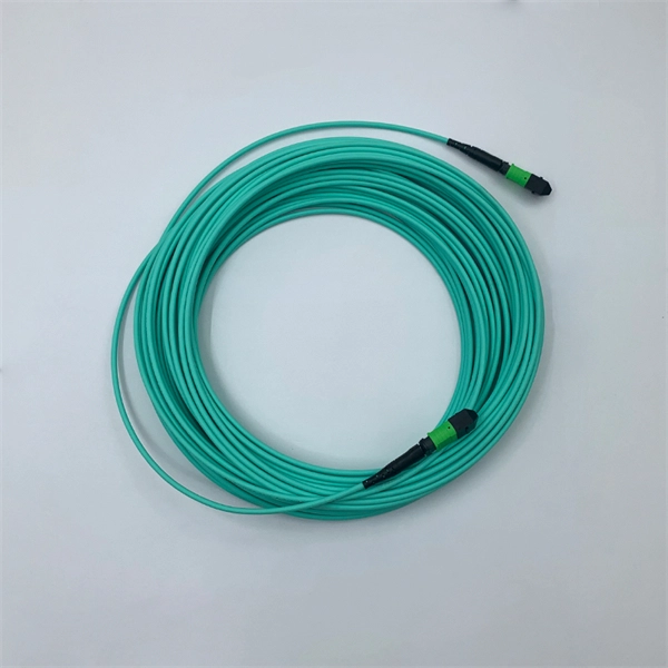
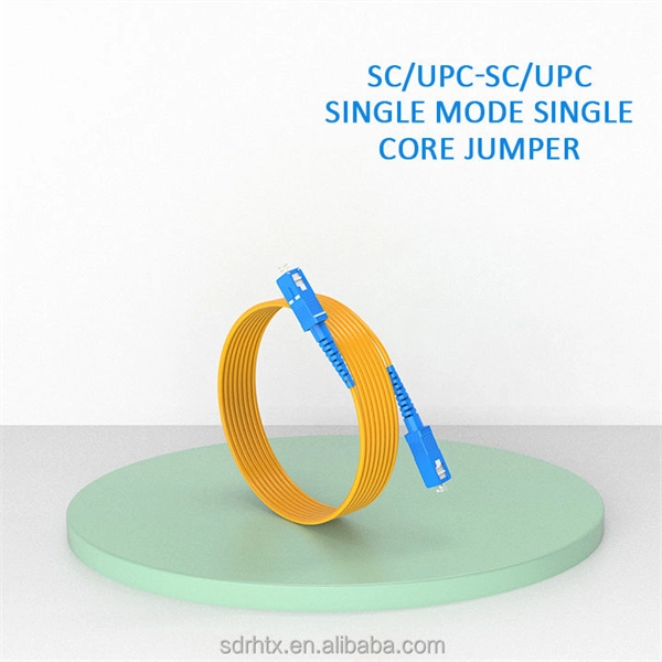
While optical fiber forms the basis of data transmission, optical fiber cables serve as the infrastructure that facilitates the deployment and protection of these delicate strands. An optical fiber cable consists of one or more optical fibers . These cables are used mainly for digital audio connections between devices. A fiber-optic cable, also known as an optical-fiber cable, is an assembly similar to an electrical cable but containing one or more optical fibers that are used to carry light. The optical fiber elements are typically. There are different types of fiber optics based on several categories as mentioned below: 1. Based on the Number of Modes Single-mode fiber: In single-mode fiber, only one type of ray of light can propagate through the fiber. Connector types play a crucial role in selecting the right cable for specific applications, as different connectors are designed for various environments, space constraints, and high-bandwidth. Communication with fiber-optics has many advantages over electrical or “wire”-based interfaces. Unfortunately, fiber has often been considered an expensive or exotic solution, limited to high-end applications that absolutely require it. 770 references sections in Chapter 2 and Art. 300 do these apply to optical fiber cables and raceways [770. For example, subsection 770. 22, which applies when.
[PDF]
The MALD-37059 is a four channel CDR with a directly modulated laser (DML) driver for use as a transmit device in optical modules. EML: Separates the light generation function from the modulation function. It uses an external modulator to shape the signal, which improves performance in high-speed, long-distance transmission. On paper, the difference looks small. In real deployments, it can completely change the behavior of a. DML refers to a directly modulated laser. This laser is also called a distributed-feedback laser diode (DFB) since it uses a distributed feedback structure. There are two modulation techniques for optical modules, DML and EML, which are briefly introduced in this article. The optical signal transmitted in the optical fiber is not constant, but is modulated, intensity changes in the optical signal, the following is a description of the characteristics. Optical transceivers primarily adopt two mainstream modulation technologies: DML and EML. This article provides a brief introduction to both. Basic Principle of Optical Transceivers The core function of an optical transceiver is to achieve optical-electrical conversion. Ethernet layer: business as usual. 400GE or 4x100GE breakout Optical channel:.
[PDF]
The project concerns the construction and deployment of a submarine cable system interconnecting five European countries (Portugal, Spain, France, Italy and Cyprus) with four North African countries (Morocco, Algeria, Tunisia and Egypt). In addition to providing a significant upgrade of the. Submarine cables are the backbone of the international electronic communications network and the life blood of world commerce. Almost all of the transoceanic Internet, electronic commercial interchange, and public communications traffic is sent via these cables. Currently Malta is connected to the. AFR-IX Telecom, an infrastructure and telecom operator in Africa, is proud to announce that it has secured new funding from the European Commission to support the MEDUSA AFRICA Submarine Cable System through CEF Digital programme. This investment marks a significant milestone in enhancing digital. The MEDUSA AFRICA project will expand high-speed, low-latency internet access, particularly in underserved coastal and inland regions. 3M to AFR-IX Telecom to expand the Medusa Africa submarine cable, enhancing Europe-Africa digital connectivity.
[PDF]

Regularly testing fiber optic cables helps minimize network downtime, lengthens the network's longevity, reduces maintenance requirements, and helps support network reconfiguration and upgrades. Fiber optic testing ensures the performance and reliability of fiber optic networks. Key tests include: Effective fiber testing utilizes advanced tools such as Optical. Fiber optic testing for continuity is crucial in ensuring that light transmits through fiber optic cables without interruptions, safeguarding seamless data transmission. This guide talks about the primary methods and tools for effective continuity testing in fiber optic cable networks. Insertion loss testing confirms whether the cable meets design loss budgets. OTDR testing identifies events along the fiber length, including: OTDR is essential for long-distance FTTH feeder and distribution cables. After the cables are installed and terminated, it's time for testing. For every fiber optic cable plant, you will need to test for continuity, end-to-end loss and then troubleshoot the problems. If it's a long outside plant cable with intermediate splices, you will probably want to verify the. We'll explain why it's vital to test fiber optic cables, the three most popular methods, and when you should use them. Why Testing Fiber Optic Cables Matters? Regular testing of fiber optic cables is not just a preventive measure; it's an.
[PDF]
Whether you're installing new fiber optic cables or troubleshooting and repairing an existing fiber network, a working knowledge of the regulations that apply to your project can help you (and your team) stay s.
[PDF]
The typical thickness of a glass core can range anywhere from 8-10 um (microns) for single-mode and 62. 5-50 um for multimode; these core sizes are the most prevalent ones utilized in the telecommunications industry. The core of a conventional optical fiber is the part of the fiber that guides the light. It is a cylinder of glass or plastic that runs along the fiber's length. The core is surrounded by a medium with a lower index of refraction, typically a cladding of a different glass, or plastic. The light is transported along the optical fiber via its smallest and most crucial component, which is called the core. However, they are composed of many components, each constructed from advanced materials to guarantee the quick and reliable transmission of data. So, let's break it down! The core is the primary part of a Fiber optic cable. It's responsible for. The 8 Core Multimode Outdoor Fiber Optic Cable is designed for high-performance data transmission in various outdoor environments, making it an ideal choice for telecommunications, networking, and data center applications. We supply single mode GYTS fiber optical cable and multimode GYTS fiber optic cable, fiber strand from 2 cores to 432 cores. A related GYTA type cable is available. This advanced cabling solution allows fast, secure data transfer and telecom over long distances. Understanding the components within a fiber optic cable enables.
[PDF]
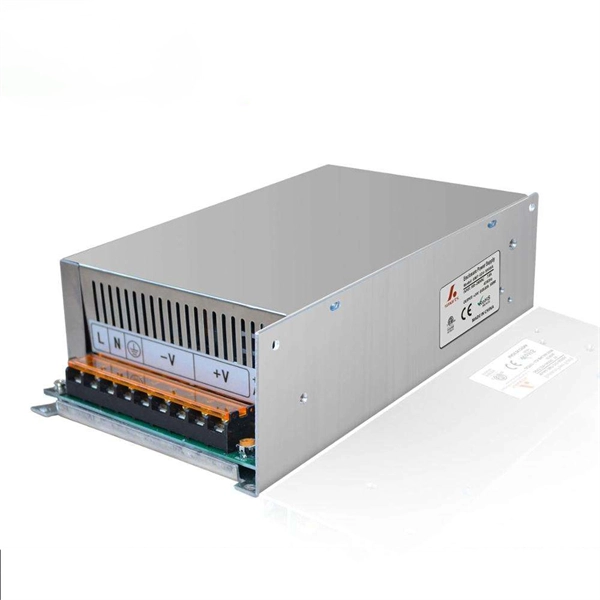
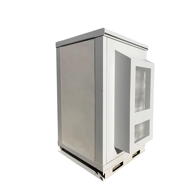
Unplug the electrical power cord of your BBU from the wall outlet. Open the battery cabinet on the BBU (you may need a screwdriver to do this). So, what DOES work for keeping track of your battery status? The right solution will help you solve the problems above without dooming you to the pitfalls above. Monitors the "Big 3" elements of battery health: voltage, temperature, and internal resistance. Provides 7x24x365 protection - without. This paper describes a step by step program of methods and procedures for maintaining the VRLA battery systems in the Local Exchange Carrier Central Office and Outside Plant Telecommunication Cabinet environments. Embracing these methods and procedures allows the user to obtain maintenance and test. Proper sizing of a telecom battery bank is essential for ensuring reliable power delivery and optimal performance. By calculating your energy needs and understanding the technical aspects of battery configurations, you can build a system that meets your requirements effectively. To size your. The DC Battery Module is a component of the DC power distribution panel for telecommunications that ensures the batteries fulfill. By understanding the methods for calculating battery capacity, charge/discharge rates, and cycle life, you can optimize the performance of your telecom cabinet power system and telecom batteries. Ensure the area is free from dust and vibrations, as these factors can affect the.
[PDF]
Understand the core function, compare data rates (1G to 25G), learn critical compatibility rules, and follow our 5-step checklist for selecting the perfect SFP optical module for your network build. SFP (Small Form-factor Pluggable) is a compact, hot-pluggable network interface module used to connect network devices (switches, routers, firewalls) to fiber optic or copper cables. Think of it as the “translator” for your network equipment, converting electrical signals into optical signals. As optical transceiver nerds, we wanted to list some of the most common SFP+ transceiver price lists to help you find the suitable optical transceiver for your needs in the easiest way possible. Optcore is a global supplier of 10G SFP+ transceivers for the ICT industry. Various 10G SFP+ models with. S+31DLC10D is a reliable, industrial-grade 10G SFP+ module designed for long-distance single-mode links up to 10 km. This modular. A practical, engineer-friendly guide to choosing the right transceiver form factor by speed, port density, power, migration plan, and operational risk—built for 25G/100G networks in 2026. 25G SFP28 is the new access/server baseline; deploy it for port density and long-term value. SFP optical modules are the unsung heroes of fiber networking—the essential interface that converts.
[PDF]
There are connectors designed for single mode and multimode fiber optic cables, which differ in core size, bandwidth, and optimal use cases as explained in this comprehensive guide to fiber optic cable t.
[PDF]

In this video, we'll walk you through the process of resurrecting y. The test sets display a laser warning icon when the laser source is active to alert the user about a potentially dangerous situation. It is recommended to: Deactivate the laser before connecting or disconnecting optical cables or patchcords. more Is your optical power meter showing no signs of life? Don't worry; we've got you covered! In. Introduction The RP460 Optical Power Meter is an ultra low cost, and compact power meter used for verifying both absolute and relative power across any given fiber. This document will serve as an overview of the major features and functions of the device and will offer tips for trouble shooting. Fiber Optical Powermeter User Manual | FS Title Author Subject Keywords Created Date. The OPM1315 is a newly developed portable optical power meter. It is equipped with a 1. 0 mm large area detector so that stability and reliability can be enhanced effectively. This unit is designed to fit the hand comfortably, and can be used for installation, debugging, and maintenance of any fiber. ments to the instrument's performance and functionality. The figures given in this manual ion of this manual to ensure the accuracy of its contents. However, should you have any questions or fi gistered users with a variety of information and services. Please allow us to serve you best by.
[PDF]

The optical module is usually composed of Transmitter Optical Subassembly (TOSA, containing a laser LD Chip), Receiver Optical Subassembly (ROSA, containing a photodetector PD Chip), a driving circuit, and an optical and electrical interface. Its schematic is shown in. This section explains the structure of a typical pigtail butterfly module, which gets its name from the two rows of seven leads at right angles on each side of the metal package plus an optical fiber pigtail at one end (Fig. Let's look at the internal structure (Fig. 2) of a common butterfly. Optical modules are devices used to connect network devices, transmit and receive data between network devices, and can be used to convert optical and electrical signals. The optical module is a very important component in an optical communication system. Optical devices are the core components of optical modules. TOSA and ROSA in Common Optical Transceiver Modules For ordinary optical transceiver modules, there are two optical devices, TOSA and ROSA, which have opposite effects.
[PDF]

This practical file details experiments conducted in Optical Fiber Communication, covering modulation techniques, system components, and performance analysis. An optical fiber is a glass or plastic fiber designed to guide light along its length, widely used in fiber-optic communication, which permits transmission over longer distances and at higher data rates than other forms of communications. Fiber-optic communication is a method of transmitting. Availability of plastic optical fiber (POF) The plastic optical fiber used in some of these experiments is available for science distributors. It is a 1000micron (1mm) POF available from several suppliers. FOA has samples available at no cost for teachers at schools in the US. Key experiments include amplitude modulation, frequency modulation, and pulse width modulation, aimed at understanding fiber optic systems. This document summarizes 10 experiments on optical fiber communication: 1. Studying a 650mm fiber optic analog link and the relationship between input and received signals. Optical fiber communication Laboratory Optical fiber communication Laboratory List of Experiments: 1. To set up a analog optical fiber link 2. To measure the characteristics of LED and LASER 5. Tech curriculum designed to provide a comprehensive understanding of optical fiber communication systems. This lab offers an immersive, web-based simulator that enables you to explore and experiment with key concepts in optical.
[PDF]

This article provides a detailed technical comparison between fiber optic and copper cables, offering a clear perspective for engineers, network architects, and procurement managers. The core distinction between the two technologies lies in the physics of data. There are significant differences in performance between ADSS cables (all-dielectric self-supporting optical cables) and traditional optical cables, which are mainly reflected in the following aspects: 1. This type of fiber optic cable is designed to support its own weight without the need for additional support structures like messenger wires. The ADSS. There are several factors to assess when deciding which cable type is right for your application, including speed of connection for new customers, ease of changes and repairs, installer certification requirements, and the ability to expand the network over time. ADSS Fiber Optic Cables are a type of optical fiber cable designed specifically for. All-dielectric self-supporting (ADSS) cable is a type of optical fiber cable that is strong enough to support itself between structures without using conductive metal elements. It is used by electrical utility companies as a communications medium, installed along existing overhead transmission.
[PDF]

Per‑unit estimates often appear as $0. 50 per ft for basic fiber plus additional charges for trenching and install labor. Several drivers shape fiber installation pricing. Homeowners and businesses typically pay for fiber optic cable installation based on distance, conduit needs, and labor. The main cost drivers include material type, run length, trenching or aerial work, and any required permits or inspections. This guide provides clear cost estimates, price ranges. The initial cost of installing fiber optic cables can vary depending on the chosen installation method and specific project requirements. Total Project Costs: For commercial installations, expect costs ranging from $5,000 to $20,000 per mile for underground projects and from $40,000 to $60,000 per. Buyers typically pay for fiber laying by combining material costs, labor time, and permitting plus trenching or aerial support fees. A short residential drop under 1,000 ft may cost $3,000-$8,000, while longer runs to an attached garage or street node can run $8,000-$25,000. The price often reflects project scope, geography, and local regulations, making. Fiber optic cable costs vary widely – from $0. Installation can be more expensive than the cable itself, especially with site challenges.
[PDF]
Here at AFL we provide years of experience and excellent solutions for your hardware needs in both ADSS (All-Dielectric Self Supporting), OPGW (Optical Ground Wire) and SkyWrap cables. Please follow the links below for assistance in choosing your hardware. The aluminum Opti-LoopTM FOS for All Dielectric Self Support (ADSS) cable is available in 3 sizes. With more than one million units in service, Opti-Loop fiber storage systems lead the industry in quality and durability. All aluminum construction with continuous welds at crossbars and ends. Each. Also see our line of ADSS Fiber Optic Cable. © Copyright 2026 AFL. Our product experts are here to assist you. Get in touch with our team now. PLP transmission, distribution, substation, fiber optic, solar, and EV solutions protect and connect overhead electric power lines and communications networks. ADSS Anchor Tension Clamps are hardware fittings used to securely terminate and anchor ADSS fiber optic cables on poles or towers without damaging the cable. This is a type of self-supporting optical fiber cable that does not require any kind of support in distributing electricity from one point to another. As much as they may be independent, these cables are usually installed on poles and.
[PDF]