When deploying fiber optics in the field, telecommunications companies need ways to safely and efficiently store and terminate cables. As many technicians know, having the right fiber optic patch and splic.
[PDF]
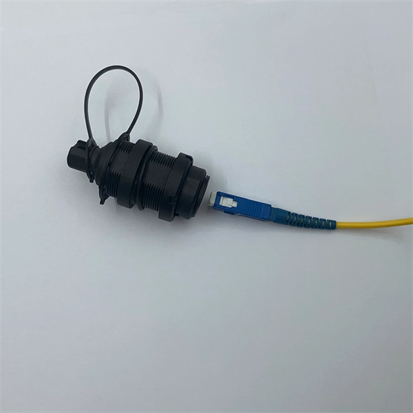
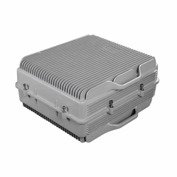
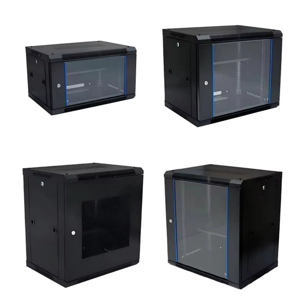
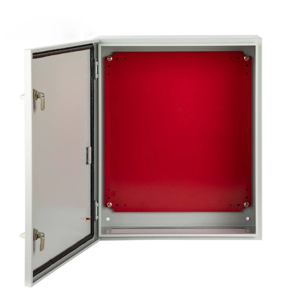
A fiber optic termination box is an enclosure designed to terminate incoming optical fiber cables and distribute optical signals to drop cables or patch cords. It integrates fiber splicing, adapter management, and cable protection in one compact unit. A fiber optic termination box, often called an optical distribution frame (ODF) or fiber patch panel, serves as the endpoint where incoming fibers connect to devices or. A fiber optic termination box is a core component in modern fiber optic networks, providing a secure and organized point for fiber termination, splicing, and distribution. It is widely deployed in FTTH, FTTB, and other access networks to ensure stable signal transmission from backbone cables to end. Fiber termination refers to the process of preparing the end of a fiber optic cable to connect to another fiber, a device, or a network. There are two primary. A Fiber Termination Box, also known as a Fiber Distribution Box, is a crucial component in fiber optic networks. It is a small enclosure that can house and protect the fiber optic cables, splices, and connectors. The fiber termination box. Choosing the right fiber optic terminal box is less about buzzwords and more about matching physics and field reality to your site: where the box will live, how many cores you need now and later, how technicians will access it, and what level of environmental and mechanical protection the network.
[PDF]

Learn how to splice fiber optic cable using fusion splicing with this complete step-by-step guide. Includes tools, best practices, loss standards (ITU-T G. 652), cost analysis, and FAQs for network engineers and installers. 5,398 fiber splicing stock photos, vectors, and illustrations are available royalty-free for download. Template technician Fiberoptic Fusion Splicing. Worker connecting for Cable Internet signal and Wire connection with Fiber Optic Fusion Splicing machine,fiber optic cable splice machine in work. Splicing fiber optic cable is an extremely important phase for making dependable, high-speed communication infrastructures. Regardless of the type of fiber network you're deploying, be it for telecom, enterprise data centers, or smart city infrastructure, fusion splicing provides the benefits of. In this guide, we cover the basics of fiber optic splicing, how to perform splicing using two different methods, and finally some best practices to perform good fiber splicing. Ensure Your Splicing Tools are Clean – #2. For network managers and technicians, a poor splice can lead to significant signal degradation, network downtime, and costly troubleshooting. At Turn-Key. 🔧 Watch a real-time fiber optic splicing demo in action! In this step-by-step tutorial, learn how to splice fiber optic cables like a pro — perfect for telecom technicians, network engineers, and field techs.
[PDF]
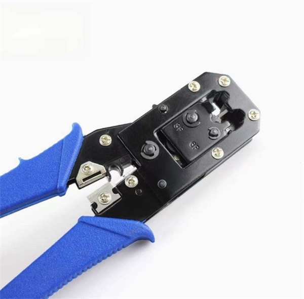
The timeframe for splicing a fiber optic cable can vary depending on the type of splice, the equipment used, and the level of expertise of the technician. In this article, we will delve into the details of the splicing process and explore the. Fiber splicing involves several steps, each requiring attention to detail and precision: The first step is to prepare the fibers for splicing. This involves: The fiber splicing process itself involves: Once the splice is complete, the technician must test the connection to ensure it meets the. Mechanical splices are faster for emergency restoration but have higher typical loss (0. 1dB for fusion) and degrade over time in outdoor environments. A professional splice kit includes: Every splice starts with proper preparation: clean the work area, protect against wind, and. Downloadable one-page analysis available from The Fiber Optic Association also offers cleaving and splicing tips. A chart developed by Fiber Optic Association master instructor Joe Botha helps technicians calculate the amount of time it will take to conduct a fusion-splcing project. The FOA. So in essence, fiber optic splicing is a process used to join two separate fiber optic cables together. There are numerous use cases for fiber optic splicing. Another method of connecting optical fibers is termination or connectorization, which consists of processing the end of a fiber optic bundle so that it can be connected to other fibers or devices through fiber optic.
[PDF]

Find certified telecom, fiber optic, and copper cable splicing contractors in Georgia. Browse the SpliceList directory for verified splice crews. From homes to businesses, Comlink Solutions delivers reliable and efficient fiber optic infrastructure tailored to your specific needs. Our team of experts provides comprehensive services, from design and planning to splicing and installation. Trust us to deliver exceptional results. Over 30 years of expertise powering the nation's largest telecom networks. Turnkey fiber optic solutions from construction to testing — delivering excellence at every stage of the network lifecycle. FiberNexxt Communications, based in Marietta, Georgia, near Atlanta, is one of the area's experienced fiber splicing companies. We specialize in projects too small for large contractors and provide post-project support. Click the button below to get started. Professional fiber optic splicing services in Georgia with complete OSP overhead construction, strand deployment, pole engineering, splicing, testing, and full QA processes engineered to support telecom, ISP, and municipal broadband expansion across the state. Tired of fiber connectivity issues slowing down your business? Our expert fusion splicing services deliver rock-solid, high-speed connections for offices, warehouses, and data centers across Georgia and Atlanta. Slow internet again? Dropped connections during critical operations? Poor quality fiber.
[PDF]
This complete guide explores everything you need to know about ODFs — from their structure, types, and key components, to installation best practices and modern design trends. Clients facing the exact demands of specialized environments—whether it's ultra-low-latency AI clusters, space-constrained military installations, or high-density telecom exchange points need more than off-the-shelf cabling. At FS, we place the customer at the heart of our operations. We are. This white paper provides a comprehensive guide to designing future-proof fiber optic networks, emphasizing a core-to-edge architectural approach. Key focus areas include backbone topologies, optical loss budgeting, standards compliance, and strategies for optimizing high-density environments like. In modern data centers and enterprise networks, Optical Distribution Frames (ODF) serve as the backbone for organizing, terminating, and managing fiber optic connections. As data centers, enterprises, telecom operators, and smart-building infrastructures deploy increasingly dense fiber links, ODFs provide the structured. Fiber optic network design refers to the specialized processes leading to a successful installation and operation of a fiber optic network. It includes first determining the type of communication system (s) which will be carried over the network, the geographic layout (premises, campus, outside.
[PDF]
This lab offers an immersive, web-based simulator that enables you to explore and experiment with key concepts in optical communication, such as signal transmission, fiber optics, modulation, and detection techniques. Opticomlib is an open source Python package for optical communications research. It is oriented to engineers who want to simulate optical communication systems using Python. The package provide binary_sequence, electrical_signal, optical_signal, and eye objects with methods for signal processing. Welcome to the Optical Communication Lab, a vital part of the B. MATLAB facilitates simulations of electromagnetic pulse propagation, saving time and resources for engineers. The study employs an ultrashort pulse with a halfwidth of 0. 65 picoseconds over a 3. PulseEvolution simulates the propagation of pulses in optical fibers by solving the NLSE using the Split Step Fourier Method. A GUI allows you to easily configure the. This study presents a novel method for simulating fiber pulse propagation using the DeepONet architecture, significantly reducing computation time compared to traditional methods. The approach is highly applicable in fields requiring real-time fiber optic system control and optimization, such as. Optical Fiber Simulation in MATLAB thesis ideas along with simulation guidance are supported by us in a very novel way for scholars if you are looking for customized services you can approach us by sharing all your project details to us.
[PDF]
In this guide, we'll walk you through the entire process of preparing fiber optic cable for splicing and termination to fiber connectors. We'll explore the necessary tools, safety precautions, and step-by-step procedures for cable connectors, mechanical and fusion. In this guide, you will find a chronological description of the fusion splicing process, the principal technical standards, and answers to the real-life questions network engineers and procurement teams may have. Therefore, we will also touch on cost factors, risk management, and best practices in. In this guide, we cover the basics of fiber optic splicing, how to perform splicing using two different methods, and finally some best practices to perform good fiber splicing. What is Fiber Optic Splicing and Why is it Needed? – #1. Two types of splices are used in fiber optic cabling one is Mechanical the other is Fusion. Before jumping into the physical steps, it's important to understand the two primary methods of fiber splicing: fusion splicing and. Learn how to splice fiber optic cable step by step in this complete guide! In this video, you'll see the full fiber splicing process — from fiber preparation, cleaving, and fusion splicing to final testing. For network managers and technicians, a poor splice can lead to significant signal degradation, network downtime, and costly troubleshooting.
[PDF]

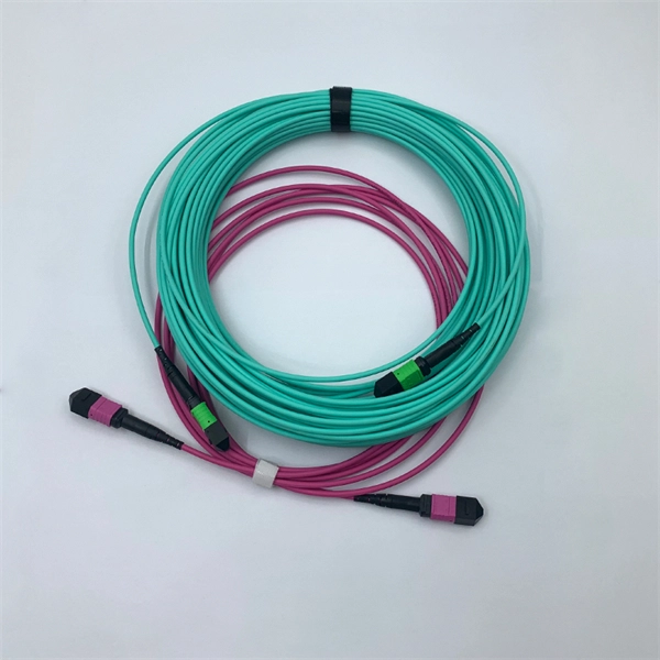
Even when a network is designed correctly, real-world conditions—fiber handling, connector cleanliness, splices, environmental stress, and aging—can gradually increase attenuation or introduce reflections and interference. Fiber optic patch cords are often treated as low-risk consumables, yet a large percentage of optical link failures originate at the patch cord level. Unlike backbone cables, patch cords are frequently connected, disconnected, bent, and handled by technicians, making them the most vulnerable. Optical attenuation is the gradual loss of flux (light intensity) as an optical signal travels through a fiber. Measured in decibels (dB), it's the logarithmic ratio of the output power to the input power. Every network has a "loss budget". Field guide for diagnosing high fiber optic attenuation. Learn to use the OTDR to identify contamination, micro-bends, and poor splices, ensuring your 400G network links remain within budget. This article explains practical, engineering-focused ways to mitigate signal. This measurement helps determine the efficiency of a fiber optic system. Several factors contribute to signal attenuation. These include absorption, scattering, and bending losses. Each factor plays a significant role in the overall performance of a network. Whether you're a network engineer, IT manager, or service provider, understanding these challenges and how to address them is critical for maintaining high-performance, reliable.
[PDF]
Distributed fibre optic sensing, including DTS and DTSS technologies, has a wide range of applications across various industries. Here are some key areas where these innovative technologies are making.
[PDF]

Access 760 verified Cable Suppliers in Morocco with shipment-level prices, volumes, routes, buyer networks, and verified decision-maker contacts — all backed by bills-of-lading. FBR CABLES designs and manufactures high-performance fibre optic cables in Morocco for operators, integrators and FTTH projects. Backed by advanced production capabilities, we deliver certified quality, controlled lead times and local technical support. The only fibre cable company in Morocco. We are a high quality fiber optic patchcords manufacturer. have several years of experience and very prestigious US European references. based in Morocco, which gives us competitive advantage compare to the other low cost. List of Fiber Optic Companies in Morocco, Suppliers, Distributors. Find and discover Cable manufacturers and suppliers for all products in Morocco, featuring details on their shipment activities, trade volumes, trading partners, and more. View all cable buyers based on products in Morocco. Here are the top-ranked fiber optic cable companies as of May, 2026: 1. Charlton Precision Products, Inc. WIN SOURCE ELECTRONICS, 3. Megladon Manufacturing Group, Ltd. What Is a Fiber Optic. Volza's Global Partner Finder scans 3. Volza's data confirms a robust and dependable Cable supply network. A total. Installation of telecom infrastructure: pylons, antennas. List of suppliers for Cabling- fiber optic networks Morocco. Request for quotes, good deals, exporters.
[PDF]

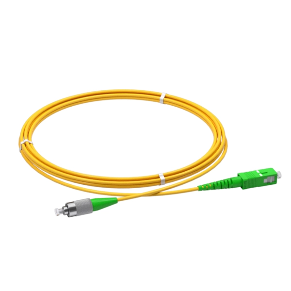
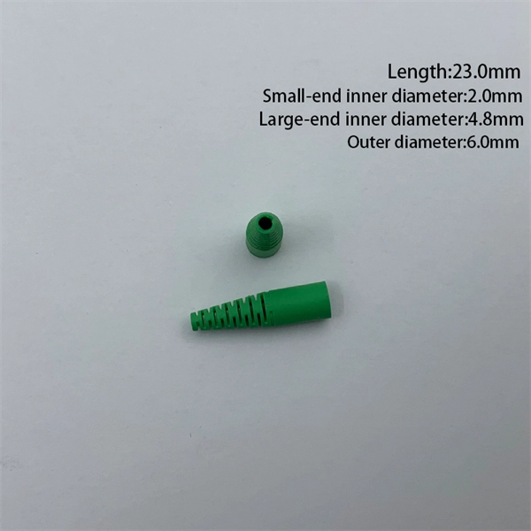
In this post, we'll walk you through practical tips, essential tools, common pitfalls, and the techniques that will help you get your fibre patch cable installations right the first time. Correct patch-cord installation is essential for maintaining low insertion loss, stable return loss, and long-term reliability in both indoor and outdoor fiber networks. Proper handling, routing, cleaning, bend-radius management, and connector alignment ensure that the optical link meets design. Proper connection of fiber optic cables is essential to harness these benefits fully, as even minor errors can lead to significant performance issues like signal loss. This guide addresses expert-certified best practices applied by professionals in the telecommunications, data. Yingda outlines the tools and materials needed to install fiber optic patch cords, as well as a complete step-by-step installation guide and important safety considerations to take. We will also tie this procedure back to the earlier discussion of multi-mode fiber types (OM1 to OM5) and connection. The Flex-Angle boot is designed to bend any angle or direction from straight to 90°. OMC flex angle boots for LC&SC fiber optic connectors are available on any single-mode or multimode patch cord. They are designed so the installer can pre-bend the boot into any direction or angle. Selecting the correct fibre patch lead is crucial for optimising signal performance and.
[PDF]

Indoor armored fiber optic cable are the latest networking infrastructure need. The cables provide ultimate mechanical protection, fire protection, and ease of installation, and thus they are suitable for indoor applications such as offices, data centers, and homes as well. These cables are suitable for both indoor and outdoor applications. Other specialized metal designs include square lock armored, spiral. In environments with high crush risk, rodents, or moisture, standard cables are not enough. What is an Armored Fiber Optic Cable? An. Supported applications include gigabit, 10 gigabit, and 40 gigabit Ethernet. Unsure Which Cables Will Suit Your Needs? What speeds and applications will this indoor armored tight-buffered plenum cable support? With bend-insensitive optical fibers (except OM1), this armored fiber optic cable is. These indoor fiber optic cables are used exclusively within buildings and must have a flame-retardant cable jacket to fit this purpose. Flame resistant cable may be deployed in-duct (conduit) or cable tray. Right selection of. Armored fiber cable is a fiber optic cable reinforced with additional protective layers to enhance its durability and resistance to external damage. These cables are designed to endure extreme environmental conditions, physical strain, and potential interference. The armor typically consists of.
[PDF]
A fiber-optic splitter, also known as a, is based on a of an integrated waveguide power distribution device, similar to a The system uses an optical signal coupled to the branch distribution. The splitter is one of the most important in the link. It is an optical fiber tandem device with many input and output terminals, especially applicable to a passive optical network (,,,.
[PDF]

Configurations of 1x1 to n x m (e., 1x8 or 2x2) are available. The insertion loss of MM switches typically amounts to approximately 0. These switches can be delivered with any of the. Multimode fiber optic switches have emerged as a crucial component, enabling seamless connectivity and efficient data transmission. The MCSW Series Multicast Fiber Optical Switches enable simultaneous connection of one input to all outputs without loss. They support fully non-blocking, conflict-free switching of any number of optical inputs to any outputs, with complete configuration flexibility. The system is entirely passive. The Siemens Scalance X204-2 Multimode Switch requires a 24V UL Listed for Fire Application, Power Limited - Regulated Power Supply. Its Input Voltage is Regulated 24VDC and its Input Current is 265mA @ 24VDC. It is powered from the battery backed up local 24V power supply. Was this helpful? Does. For extremely precise measurement systems and sensor applications as well as for telecommunication applications LASER COMPONENTS offers fiber optical multimode (MM) switches with a fiber core diameter of 50 µm to 600 µm. There are switches are for all different kinds of requirements. Configurations. CONFIGURING THE SWITCH IN DESIGO CC/CERBERUS DMS. CYBERSECURITY DISCLAIMER.
[PDF]