Use our currency converter to find the live exchange rate between KPW and USD. Convert North Korean Won to United States Dollar. North Korean financial markets allow the buying and selling of North Korean financial instruments in North Korea and is referred to as the North Korean financial market. It acts as a North Korean platform for North Korean and international buyers and sellers to connect with one another and engage. 100 currencies available to transfer to 200+ countries. The Drift Protocol hack (USD 285 million, April 1) involved three weeks of pre-attack staging and months of. The legal framework governing securities in North Korea has historically been sparse and heavily influenced by the country's unique political and economic ideologies. Following the establishment of the Democratic People's Republic of Korea (DPRK) in 1948, the state maintained stringent controls. We found 11 online brokers that are appropriate for Trading North Korea Brokers Platforms. Trading in North Korea presents a highly unique and challenging environment due to its heavy restrictions and limited access to global financial markets. The country's financial instruments are mostly limited. Total Crypto Hack Value in 2026 market is currently assessing scenarios, with potential implications of decreased cryptocurrency hack values due to enhanced defenses. Bitcoin price markets for May 4 and May 5 remain unaffected by this news, with odds stable. ## Key Takeaways – Ripple's action.
[PDF]
Den här guiden går igenom allt du behöver känna till när du vill koppla din egen router till fiber, vilka alternativ som finns, vilka inställningar som krävs och hur du felsöker om något inte fungerar som det ska. However, setting up a fiber optic connection to your router can seem daunting if you're unfamiliar with the process. In this guide, we'll walk you through how to connect a fiber optic cable to a router safely and efficiently. Why Use Fiber Optic Internet? Before diving into the setup, let's quickly. Setting up a fiber internet connection requires understanding key hardware components and following a specific connection sequence to establish your home network. This comprehensive guide combines industry standards with field-tested practices to ensure you achieve a rock-solid.
[PDF]

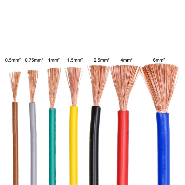
In the 2020 NEC ®, no more than 18 inches of cable length is allowed between the cable entry to the box and the closest cable support (see image). Below is a preview of the NEC®. ORG for the complete code section. The previous code language could technically allow an unlimited length of coiled up NM cable inside the wall as long as it was secured within 12 inches of the box. This code is based upon the type of box, wires, wire sizes, wire clamps and conduit fittings. Adjustments are made for the ground wire as you will see in the. Calculate and select the right number and spacing of cables for junction boxes using NEC guidelines to ensure safe, code-compliant electrical installations. This step keeps your project safe and. According to the National Electrical Code (NEC), the conductor must be long enough to extend outside the box's opening. This length allows enough room to connect, splice, or terminate wires without strain or damage. If wires are too short, they may fail inspection or create hazards during. The length of wire left inside an electrical box is a matter of strict compliance, safety, and functionality. Having the correct amount of slack ensures that future maintenance, repairs, or device replacements can be performed without difficulty. Proper electrical box fill calculations are critical for code compliance and safety in both residential and commercial installations.
[PDF]

Average Optical Power: How bright the light is (measured in dBm). Too dim? Your signal gets lost in the fiber. Extinction Ratio: The difference between “on” (1) and “off” (0) light power. A higher ratio = cleaner signals. Transmitter Side: An electrical signal hits a laser diode (LD) or LED, which spits out light. Receiver Side: Light enters a photodetector (like a tiny solar cell), which turns it back into electricity. A built-in amplifier boosts the signal for your. The average transmitted optical power refers to the optical power output by the light source at the transmitting end of the optical module under normal working conditions, which can be understood as the intensity of light. In communication, we usually use dBm to represent optical power. However, in practical use, we adopt the average Tx power. The transmission power is related to the. This article provides an in-depth analysis of two key performance indicators of optical modules: transmitter power and receiver sensitivity. Transmitter power characterizes the average optical power output from the laser under rated conditions, while receiver sensitivity indicates the minimum. An optical module is a connecting module that serves as an optical-electrical conversion device. At the receiver end, the optical signals are reconverted into electrical.
[PDF]
This blog explains how to use Kubernetes resource quotas for efficient resource management. It covers key concepts, step-by-step implementation, YAML examples for Pods, PVCs, ConfigMaps, and tips for monitoring, troubleshooting, and optimizing quotas. On the Quota Management node of the File Server Resource Manager Microsoft ® Management Console (MMC) snap-in, you can perform the following tasks: Create quotas to limit the space allowed for a volume or folder, and generate notifications when the quota limits are approached or exceeded. Generate. Service Quotas is a service for viewing and managing your quotas easily and at scale as your AWS workloads grow. Quotas, also referred to as limits, are the maximum number of resources that you can create in an AWS account. What Are Resource Quotas in. Resource quotas are a tool for administrators to address this concern. A resource quota, defined by a ResourceQuota object, provides constraints that limit aggregate resource consumption per namespace. A ResourceQuota can also limit the quantity of objects that can be created in a namespace by API. Disk quotas allow Windows administrators to control and limit the amount of disk space that users use on the file systems of servers and workstations. Windows Server supports two types of disk quotas: File Server Resource Manager quotas and NTFS quotas.
[PDF]

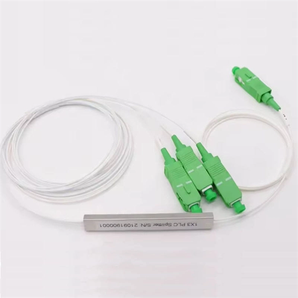
In this blog, we will explore the step-by-step process of using a beamsplitter cube effectively, along with some common applications that benefit from this powerful optical tool. Step-by-Step Guide on Using a Beamsplitter Cube. A beam splitter is an optical device that divides an incoming light beam into two separate beams. One beam is typically reflected while the other is transmitted. The ratio of reflected to transmitted light can vary based on the design of the beam splitter. Beam splitters typically come in the form of a reflective device that can split beams into exactly 50/50, half of the beam being transmitted through the splitter and half being reflected. It is a crucial part of many optical experimental and measurement systems, such as interferometers, also finding widespread application in fibre optic telecommunications. Sometimes it is referred to as a half-silvered mirror. Either way, it is a simple material that YOU could use right at home for cool DIY projects like. The beam splitter has played numerous roles in many aspects of optics. For example, in quantum information the beam splitter plays essential roles in teleportation, bell measure-ments, entanglement and in fundamental studies of the photon. Additionally, beamsplitters can be used in reverse to combine two different beams into a single one. Beamsplitters are often classified according to their construction: cube or plate.
[PDF]
If a steel cable tray costs $5 per meter, the cost per foot would be approximately $1. The average cable tray price per meter ranges from $2 to $25, depending on material, type, size, and surface finish. 👉 For bulk orders or project pricing, the cost can be significantly lower. The main cost driver is the material used in manufacturing: 🔹 Galvanized steel is the most common. Although metal pipes (conduit) may appear cheap initially, they tend to be the most costly option when the job is finally complete, since they consume a lot of time to install. Here is how the three main systems compare when looking at the total bill. Why is Conduit So Expensive? Wires go through a. How can we improve? Choose from our selection of ladder cable trays, including cable and hose trays, heavy duty open cable and hose carriers, and more. Same and Next Day Delivery. Aluminum cable ladders are easy to install and cost less than steel cable ladders. Their lightweight construction makes them easy to work with and transport. This is advantageous because it saves on installation costs and time. Cable trays are vital in electrical installations, providing secure pathways for power, communication, and control cables across residential, commercial, and. Cable ladder trays have side rails with rungs to route and support cable. These trays also provide free air flow to prevent overheating, which could damage the cable. They mount overhead or under.
[PDF]

Get answers to frequently asked questions about broadband services at BTC Bahamas. At Lightcommunication Company, we specialize in comprehensive fiber optic solutions, ensuring superior connectivity through expert services in installation, splicing, and network maintenance. We strive to revolutionize communication by providing cutting-edge fiber optic services that empower. BTC, also known as the Bahamas Telecommunications Company, is the national telecommunications company of the Bahamas. It offers a range of internet services, including fibre optic and DSL connections, and has a wide network of fibre optic cables, allowing it to provide high-speed internet to both. Clear Fiber Technology Solutions is a leading and reputable Telecommunications Contracting and Consulting Firm serving the Bahamas and Caribbean area. We understand the importance of Professional and Reliable Communications Services. We take a comprehensive approach to secure solutions, providing. Our aim is to provide reliable, cost effective, comprehensive solutions with efficient service to assist you in building I. infrastructure you can depend on. We want to be your partner of choice. call on us when you need to build out, upgrade or expand. Along the way we make it our mission to enrich lives and businesses through reliable, fast and future ready technology. Cable Bahamas nurtures education, wellness and cultural growth through dedicated partnerships and.
[PDF]

Yes, you can unplug your fiber optic cable, but it's crucial to do so with extreme care to avoid damage, contamination, and service interruption. Fiber optic cables are delicate and require specific handling procedures to maintain their performance and longevity. However, situations may arise requiring you to disconnect these specialized cables from modems or routers. Fiber optic cables transmit data. Unplugging a fiber optic cable from a modem is a task that requires careful handling to avoid damaging the delicate fibers within the cable. Fiber optic cables are different from traditional copper cables, as they use light to transmit data, and the connectors are more sensitive. Is this something that requires a Verizon support tech or can I do it? If so is it as simple as disconnecting and reconnecting or would I have to call support to "reinitiate" my setup. Not my pic, but didn't feel like moving the. In this video, I'm showing you how to remove an optical fiber cable connector from a modem. This is a popular video tutorial that is often requested by viewers. This guide will help you safely and effectively remove a.
[PDF]
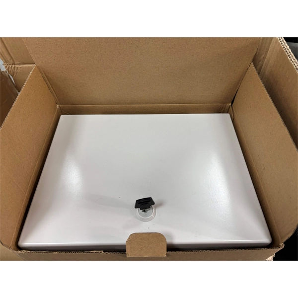
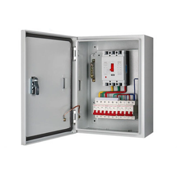
Learn the step-by-step process of customizing complete distribution boxes tailored to your needs. From requirement confirmation to design, production, and testing, find out how to get a reliable, flexible distribution system. These versatile units are like the Swiss Army knives of electrical systems – compact, adaptable, and incredibly efficient. But let's be honest, even the best tools can turn into headaches if we don't install. CSS Flexbox is short for the CSS Flexible Box Layout module. Flexbox is a layout model for arranging items (horizontally or vertically) within a container, in a flexible and responsive way. Distribution box refers to the equipment used in the power distribution. Our comprehensive guide to CSS flexbox layout. This complete guide explains everything about flexbox, focusing on all the different possible properties for the parent element (the flex container) and the child elements (the flex items). It also includes history, demos, patterns, and a browser. Our flexible distribution boxes enable reliable, decentralised signal transmission and power transmission up to protection class IP67 – wherever passive distribution boxes are required. From power and signal distribution to I&C applications and complete room solutions - we have just what you need. Our solutions enable short planning and realization times and allow optimized.
[PDF]
This guide dives deep into the most prevalent fiber optic network problems, their root causes, and actionable solutions. Fiber optic technology is essential for modern communication, offering unparalleled speed, reliability, and efficiency. However, improper installation can lead to severe performance issues, expensive repairs, and unnecessary downtime. To ensure a high-functioning fiber optic network, avoid these. Understanding the common causes of failure and implementing preventive measures is essential to maintaining reliable networks and avoiding costly downtime. In this article, we explore the primary modes of field failure in fiber optic cables and outline best practices to prevent them. This article outlines three key errors and how to avoid them.
[PDF]

Professional Cable Tray Elbow Making | Metal Fabrication Tutorial Learn how to make cable tray elbows professionally with step-by-step guidance. This video shows metal fabrication techniques, DIY cable tray projects, and tips for perfect bends and joints. Whether you are a DIY enthusiast. The method for producing bridge bend elbows is as follows: Take a 90-degree cable tray bend elbow as an example, and apply the same principles for 45-degree bends accordingly. The length of the bottom side (bottom diagonal) after bending the cable tray should be equal to the width of the cable. This manual is designed to guide workers through the detailed production process of ladder cable trays, including the manufacture of horizontal elbows, tees, crosses, reducing bends, and vertical bends, with emphasis on precision, safety, and quality control. What's Involved in Producing Ladder. The bends, tees, crosses, risers and reducers of wire mesh cable tray can be easily and quickly made live at the project by using a bolt cutter. Since the jaws of the bolt cutter drags a layer of zinc across the cut end and forms a protective layer. When a wire cable tray is cut, the fact that a. How to bend 22. 5 DEGREE OF CABLE TRAY 3 LA. How to bend 90 degree of cable tray 3 line with the same distance :// • HOW TO BEND 90 DEGREE OF CABLE TRAY 3 LINE. Enjoy the videos and music you love, upload original content, and share it all with friends, family, and the world on YouTube.
[PDF]

In this video, we'll walk you through the process of wiring a home distribution box with a detailed connection diagram. Whether you're an electrician or a DIY enthusiast, this guide will help you understand the basics of home electrical distribution. more Welcome to our channel! In this video. Single Phase wiring installation is the most common wiring in residential buildings. In Single Phase supply (230V in UK, EU and 120V & 240V in the US & Canada), there are two (one is Line (aka Phase, Hot or Live) and the other one is Neutral) incoming cables from the utility poles to the kWh energy. A distribution board or distribution box is where the main power supply is distributed to multiple loads. And all the switching and protective devices are installed in the distribution box. Single Phase Distribution Box generally consists of Double Pole MCBs, Single Pole MCBs, and RCCBs. An electrical panel box, also known as a breaker box or a distribution board, is a crucial component of any electrical system. It serves as a central hub for distributing electricity throughout a building, ensuring that power is delivered safely and efficiently to all the required locations. What is Distribution Board? Distribution board.
[PDF]

The first thing you should do is locate the fiber optic cable that comes from the service provider. Once inserted, make sure it is securely. However, setting up a fiber optic connection to your router can seem daunting if you're unfamiliar with the process. Why Use Fiber Optic Internet? Before diving into the setup, let's quickly. Ensure your fiber optic router has an available WAN (Wide Area Network) or Ethernet port for the fiber optic modem. It's thin, flexible, and usually comes with connectors on both ends. Power Cables: Get power cables for both the. The fiber optic cable does not plug directly into a standard home router because the signal type must be translated. The fiber line terminates at the Optical Network Terminal (ONT), which is typically supplied and installed by the internet service provider. This specialized equipment serves as the. The process to connect fiber optic cable to router requires careful attention to detail, but I'll walk you through every critical step with the precision and clarity you deserve. Here's a step-by-step guide to help you through it. Understand the Basics Before diving in, familiarize yourself with the components involved:. Follow along as we take you through the step-by-step process of installing fiber internet! From preparing the site to connecting the final cables, we'll show you what goes into bringing high-speed internet to your doorstep. Whether you're a tech enthusiast or just curious about how it all w.
[PDF]

Optical modules (also known as fiber optic transceivers) are essential components in modern communication networks, enabling high-speed data transmission by converting electrical signals into optical signals and vice versa. Among various optical module form factors, SFP (Small Form-Factor Pluggable). A fiber optic transceiver (also called an optical transceiver) is a compact module that both transmits and receives data signals through optical fibers. It serves a dual purpose — transmitting electrical signals as light pulses and receiving light pulses to convert them back into electrical form. An optical module usually consists of an optical transmitting device (TOSA, including a laser), an optical receiving device (ROSA, including a photodetector), functional circuits,main control circuit board (PCBA), housing and optical (electrical) interface and other components. How do optical. At the heart of fiber optic technology lies a crucial component: the optical transceiver. Let's explore the key aspects of optical transceivers to help you navigate.
[PDF]

