
The maximum split ratio of the FBT splitter is as high as 1:32, which means that one or two inputs can be divided into outputs of up to 32 optical fibers. By dividing a single optical signal from a central Optical Line Terminal (OLT) into multiple outputs for Optical Network. In this guide, you'll learn how fiber splitters function in PON networks, the difference between PLC and FBT types, and how to choose the best model for your rollout in 2025. What Are Fiber Optic Splitters in PON? Fiber splitters are passive devices that divide one optical input signal into. FTTH relies on Passive Optical Network architecture, which enables one fiber leaving the central office to serve multiple subscribers through optical splitting. This structure eliminates the need for powered elements in the distribution segment, reducing operational costs while ensuring high. Optical splitter is an integrated waveguide optical power distribution device that serves to split optical signals. It is widely used in passive optical networks (such as EPON, GPON, BPON, FTTX, FTTH, etc. ) and plays an important role. When an optical signal is transmitted in a single-mode fiber. The FTTH network serves as the infrastructure enabling data transmission in the form of light signals over optical fiber from the operator's switching equipment directly to a home or business. Accurately understanding the principles, differences, and applicable boundaries of.
[PDF]
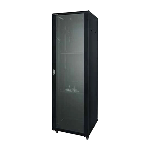
Rack height is measured in rack units (U), where 1U equals 1. Common rack formats include: 24U and below — typical for branch offices or small server rooms. Below is a comprehensive, fully detailed guide covering all standard server rack sizes, form factors, height considerations, depth classifications, and best-practice configuration approaches for professional environments. What Is a Server Rack? Understanding the Core Structure A server rack is a. This comprehensive blog post demystifies the "U" unit in network server accessories—the standard measurement that defines the height of equipment in server racks. A 2U server occupies two rack units, while a 4U server takes up four. Each rack is equipped with mounting rails. A “Rack Unit” (U) is a standard height measure for mounting equipment in a server rack. This article explains definition, planning, installation tips, and trends. At Secure Gates Inc., we provide high-quality 6U, 9U, and 12U Network Rack Cabinets designed to meet the unique needs of professionals, businesses, and data centers. In this blog post, we'll explore what network rack cabinets are, their key benefits, and help you decide which size— 6U, 9U, or 12U. U (rack unit, RU) is a unit of equipment height in a 19" rack. Important: U describes height only, but a server's real "capabilities" are also determined by chassis depth, internal layout, airflow, rails, power, and expansion (PCIe/risers, NVMe.
[PDF]
Encuentra opciones de almacenamiento y organización en Gabinetes, Racks Servidores y Sistemas de Cableado Estructurado para Redes de Voz y Datos de calidad. Optimiza tu red en Costa Rica. DURABLE - Crafted from cold-rolled steel with a protective black powder coating, the 6U NavePoint Performance Series network cabinet provides sturdy, reliable housing for network and server equipment. Capable of supporting up to 130 lbs, it's an ideal, durable solution for installers working on. TecnoBonilla. com es la mejor fuente para Rack Servers en Costa Rica. Para más información, póngase en contacto con nosotros en 6286-7654.
[PDF]
Learn how to document your sales channels and distribution patterns to find 3PLs built for your channel mix. DTC, wholesale, retail, and marketplace each require different fulfillment capabilities. Distribution channels are the paths that products and services take when moving from the producer to the consumer. The three main types of distribution channels are direct, indirect, and hybrid. The right distribution channel for you may involve intermediaries like distributors, wholesalers, and. How do businesses get products to you? Well, through distribution channels. Ever felt like a competitor is beating you simply because they appear everywhere? From wholesalers to big-name department stores, those brands. Understanding distribution channels is essential for any business aiming to effectively deliver products and services to customers. This article explores the different types of distribution channels, their roles in the marketing mix and how businesses can choose the right approach to maximize reach. Sales channels and distribution strategies are critical elements of a business's growth.
[PDF]
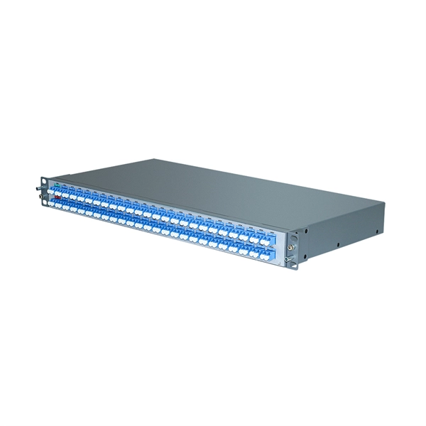
The typical cost of 1U space in a 45U server cabinet is $55. Therefore: Average cable management cost is . Basic cable management systems (cable trays, ties): $200 to $1,000 per rack. Power and Cooling Infrastructure Power Distribution Units (PDUs): $200 to $1,500 per unit, depending on capacity. 73/U The. Durable & Easy to Install: Made from sturdy plastic for long-term use in IT environments. Installs easily on standard rack rails using the included M6 screws-no special tools required Each item has a unique code that we verify before shipping. com Return Policy: Amazon. com. Sysracks offers a wide array of data closet cable management products for different devices: Horizontal managers: Our 1U wire managers are designed to suit any 19” cabinet. This allows structured routing of twisted-pair wires and patch cords and ensures the correct cord radius to prevent twisting. Shop top-quality rack cable managers for efficient data center wiring. Get a horizontal/vertical cable manager to safely organize and protect your cables. Our 1U and 2U cable managers reduce slack, improve airflow, and create clean, serviceable rack layouts designed for scalability.
[PDF]
This guide provides instruction on how to install and configure your MS130R series switch. For more switch installation guides, refer to the switch installation guides section on. This guide provides step-by-step instructions for installing two common types of industrial switches: rack-mount, and DIN-rail switches. Choose the Installation Location: Select an appropriate spot on the DIN rail for mounting. This chapter describes how to start your switch and how to interpret the power-on self-test (POST) that ensures proper operation. No prior experience needed—just follow along and you'll have your switch installed and running in minutes. more In this video you'll see a complete, step-by-step guide to mounting. This typeface indicates command syntax, or represents information as it is displayed on the screen. When you see the word enter in this guide, you must type something, and then press the Return or Enter key. Do not press the Return or Enter key when an instruction simply says type. Here, we explore the four most common installation methods for industrial switches: Desktop installation is the most straightforward approach— placing the switch like a small box directly on a table, control panel surface, or equipment rack without extra fixtures. Simple setup: No tools required.
[PDF]
Download a comprehensive set of Cable Tray Installation CAD Blocks in DWG format, ideal for electrical engineers, MEP designers, and industrial layout planners. Electrical cable tray layout is a ready-to-use CAD block perfect for building services, industrial setups, and electrical projects. This cable tray CAD block is compatible with AutoCAD and other DWG-supported software, allowing precise placement and easy integration into your designs. Save time and. Discover all CAD files of the "Cable trays" category from Supplier-Certified Catalogs ✅ SOLIDWORKS, Inventor, Creo, CATIA, Solid Edge, autoCAD, Revit and many more CAD software but also as STEP, STL, IGES, STL, DWG, DXF and more neutral CAD formats. This collection includes installation details for ladder trays, perforated trays, solid-bottom trays, and wire mesh trays, along with. Tray installation details for the location of a project's electrical wiring; in addition to blocks with different angles that allow the wiring circulation to be identified. Download this FREE 2D CAD drawing of CABLE TRAYS including various widths. This autocad drawing can be used in your mechanical design CAD drawings. dwg format) Our CAD drawings are purged to keep the files. Already Subscribed? Download free cable trays in DWG or CAD block format. Cable tray details.
[PDF]

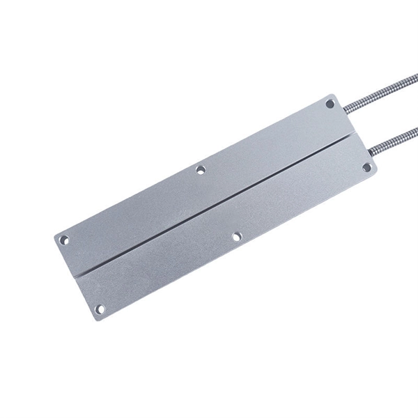
How often you check the enclosure depends on where and how you use it. You must follow rules for dangerous. Explosion proof distribution boxes and electrical enclosures are critical components for ensuring safety in hazardous environments. They are designed to contain internal explosions and prevent ignition of surrounding flammable gases or dust. Since the ATEX Directive came into force, equipment for explosive. We supply certified explosion proof distribution box & Atex Transformer -Appleton, ATKON, CZ, CEAG, brands for safe and reliable industrial use. Flameproof enclosure (Ex d IIB+H2), which can be used as feed distribution equipment in control and distribution system (such as distribution box, switch box of main circuit, control box, terminal box or motor starting box etc. ) ·Enclosure: stainless steel. Equipped with specialized hinge. Ex Industries (exindustries) is a global supplier of advanced hazardous area solutions, offering a wide portfolio of certified products including explosion proof electrical boxes, explosion proof junction boxes, explosion proof lighting, intrinsically safe barrier systems, explosion proof cables. These NEC-rated enclosures are often used to protect your people and parts from explosive risks in plants that handle or make fuel, bulk powders, and chemicals. Plus, they lock out water to keep your electrical components dry. Lift-Off Cover— The removable, screw-secured cover is best for full.
[PDF]

Check the electrical load and ensure that the sensors do not exceed the 10 Amp maximum. Check each wire for damage that may lead to a short. Check the tightness of electrical connections along the power. Issue: Frequent tripping of circuit breakers is one of the most common issues in distribution boards. It can occur due to overloaded circuits, short circuits, or ground faults. Solution: Identify the Cause: Check if the breaker is tripping due to overloading. Internal Inspection Open the distribution box and check for dust and debris accumulation. Inspect circuit breakers for proper operation. Ensure all connections are tight and secure. Each circuit breaker protects a specific circuit in your home, preventing excessive current from damaging wiring and. MDB is panel under power distribution system which consists of a fuse, circuit breakers and ground leakage protection units. Where electrical energy is taken from a transformer or an upstream panel to distribute electrical power to numerous individual circuits or consumer points. Various types of panels exist in every electrical.
[PDF]

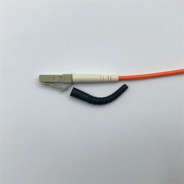
As fiber optic cables are generally only produced in lengths up to around 5 km, so when lengthier connections are needed, splicing two cables together becomes necessary. So in essence, fiber optic splicing is a process used to join two separate fiber optic cables together. There are numerous use cases for fiber optic splicing. As. The time it takes to splice a fiber optic cable can vary depending on several factors, including the type of splice, the equipment used, and the level of expertise of the technician performing the splice. Proper termination is essential for ensuring optimal performance, reducing signal loss, and maintaining the durability of the connection. Another method of connecting optical fibers is termination or connectorization, which consists of processing the end of a fiber optic bundle so that it can be connected to other fibers or devices through fiber optic. Fiber optic joints or terminations are made two ways: 1) splices which create a permanent joint between the two fibers or 2) connectors that mate two fibers to create a temporary joint and/or connect the fiber to a piece of network gear. Either joining method must have three primary characteristics.
[PDF]

In this video, we'll walk you through the process of wiring a home distribution box with a detailed connection diagram. Whether you're an electrician or a DIY enthusiast, this guide will help you understand the basics of home electrical distribution. more Welcome to our channel! In this video. Single Phase wiring installation is the most common wiring in residential buildings. In Single Phase supply (230V in UK, EU and 120V & 240V in the US & Canada), there are two (one is Line (aka Phase, Hot or Live) and the other one is Neutral) incoming cables from the utility poles to the kWh energy. A distribution board or distribution box is where the main power supply is distributed to multiple loads. And all the switching and protective devices are installed in the distribution box. Single Phase Distribution Box generally consists of Double Pole MCBs, Single Pole MCBs, and RCCBs. An electrical panel box, also known as a breaker box or a distribution board, is a crucial component of any electrical system. It serves as a central hub for distributing electricity throughout a building, ensuring that power is delivered safely and efficiently to all the required locations. What is Distribution Board? Distribution board.
[PDF]

While optical power meters are the primary power measurement instrument, optical loss test sets (OLTSs) and optical time domain reflectometers (OTDRs) also measure power in testing loss. TIA standard test FOTP-95 covers the measurement of optical power. This measurement is the basis for loss measurements as well as the power from a source or presented at a receiver. Typically both transmitters and receivers have receptacles for fiber optic connectors, so measuring the. You need a power meter to measure power in a fiber optic system; most power meters come with a screw-on-adapter that matches the connector being tested and a little aid from the network electronics to turn on the transmitter. During the measurement of power, the meter must be set to the proper. Fluke Networks sets the standard in network testing with its advanced range of fiber optic power meters and fault locators, designed to ensure the highest precision in fiber optic meter readings and power evaluations. This is measured in decibels (dB). Splitters, fusion splices, connectors and. To use a power meter for fiber optic testing, always clean connectors first with lint-free wipes or click-to-clean tools. Select the correct wavelength and set your reference. Consistent procedures ensure accuracy.
[PDF]

With the large variety of beamsplitters available, the designer needs to take many factors into consideration. This article and its illustrations will go a long way toward making the correct choice less of a risk. All curves show typical performance. A beam splitter (or beamsplitter, power splitter) is an optical device which can split an incident light beam (e. a laser beam) into two (or sometimes more) beams, which may or may not have the same optical power (radiant flux). It is a crucial part of many optical experimental and measurement systems, such as interferometers, also finding widespread application in fibre optic telecommunications. One beam is typically reflected while the other is transmitted. Beamsplitters are often classified according to their construction: cube or plate. In this blog, we will explore the step-by-step process of using a beamsplitter cube effectively, along with some common applications that benefit from this powerful optical tool. Step-by-Step Guide on Using a Beamsplitter Cube Step 1: Understanding the Cube Orientation: A beamsplitter cube is a. A beam splitter is an optical device that splits beams (such as laser beams) into two (or more) beams. Beam splitters typically come in the form of a reflective device that can split beams into exactly 50/50, half of the beam being transmitted through the splitter and half being reflected.
[PDF]

In order to help, we put together a short list to help you at least figure out how much a “class” of laser diode might cost. This list is a rough guide of pricing by package style and output power for 808, 915, 940, 980nm devices. Semiconductor laser diodes range widely in price based on a few key parameters. The wavelength, power, spectral qualities, package type, cavity type and quantity will all have an effect on the price. You can buy a laser diode for less than a dollar. But the price can also be in the tens of. Creality Falcon A1 10W Laser Engraver Enclosed Laser Cutter for Wood Metal ect. Get the best deals for 100W Laser Diodes at eBay. We have a great online selection at the lowest prices with Fast & Free shipping on many items!. Check each product page for other buying options. Need help? Discover powerful 100W laser engravers and cutters for wood, acrylic, leather, and more. Find precision machines for professional and DIY projects. A 100-watt laser diode represents a high-power semiconductor device capable of producing intense, coherent light used across industrial, medical, telecommunications, and defense applications. These diodes vary significantly in design and beam characteristics, allowing engineers to select the. DIY CNC Upgrade Module & Kit 100W MULTICOLOR 100watt Eliminator E-143 Asteroid Stage Lights. Light Move With Music Professional Laser Diode Hyperpigmentation System with Treatment Gel Kit. With power ranges.
[PDF]
This article will provide an in-depth analysis of outdoor cable types, key selection criteria, core installation steps, critical precautions, as well as subsequent testing and maintenance guidelines, helping you build a robust and durable outdoor optical communication link. Therefore, understanding the characteristics of outdoor fiber optic cables and mastering proper installation methods is crucial. Plan your outdoor fiber installation carefully by surveying the site, choosing the right cable type, and following FOA and OSP standards to ensure reliability. In this video, we'll walk you through the process of establishing a robust outdoor fiber connectivity solution. Follow our guide and establish a r. more Welcome to. Running a cable through an exterior wall can be a daunting task for many homeowners, but with the right tools and techniques, it can be done efficiently and safely. With the increasing demand for high-speed internet and reliable networking, it's essential to know how to properly install CAT 6 cables outdoors. In this article, we'll take you.
[PDF]
