
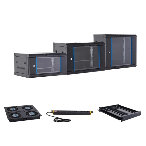
In this guide, I'll walk you through everything you need to know about choosing the right cable trays for your cables. Whether you're dealing with power cables, control cables, or communication cables, I'll break it down step by step. A 50 mm cable tray is used to organize and protect cable routes in industrial, commercial, and infrastructure facilities. This compact solution is suitable for power distribution lines, low-current systems, and engineering communications. Mirankul Group manufactures cable trays in Uzbekistan. Accessories for cable systems include a variety of different components necessary for the proper functioning of cable routes. They provide a structured and secure pathway for cables, ensuring organized installation and easy maintenance. Cable Trays are important for ensuring the protection of the wiring system and supporting insulated electric cables used for distribution and communication. Brilltech Engineers Pvt. Understand Your Cable Tray Requirements Before selecting a cable tray, consider the following key factors:. Selecting cable trays can feel overwhelming, especially with so many options available. But don't worry—I've got you covered.
[PDF]

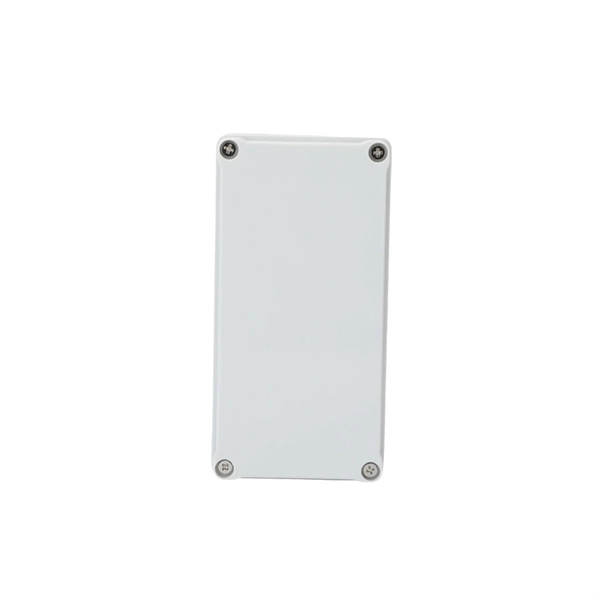
Follow a step-by-step process: mark the location, drill holes, insert anchors, and secure the box for a weatherproof fit. Apply weatherproof sealant around the box edges and cable entry points to prevent water ingress. Installing an electrical box on an exterior wall can seem daunting, but with the right guidance, it can be a straightforward task. Whether you are adding an outdoor outlet for convenience or setting up lighting, understanding the process is key. This guide will walk you through the essentials of. An electrical junction box is a protective housing designed to enclose and shield electrical wire connections or splices. For outdoor installations, the box must defend these sensitive splices against moisture, dust, temperature fluctuations, and physical impacts. Safety remains crucial during installation. It takes the incoming power and safely distributes it to different circuits throughout your building. Whether in a home or an industrial facility, this box keeps your electrical setup organized, functional, and efficient. Whether adding a GFCI outlet for safety or upgrading an exterior outlet for weather-resistant durability, it's essential to follow proper electrical wiring. In this video, I'll show you how to install a weatherproof outdoor electrical box — safe, secure, and code-compliant.
[PDF]

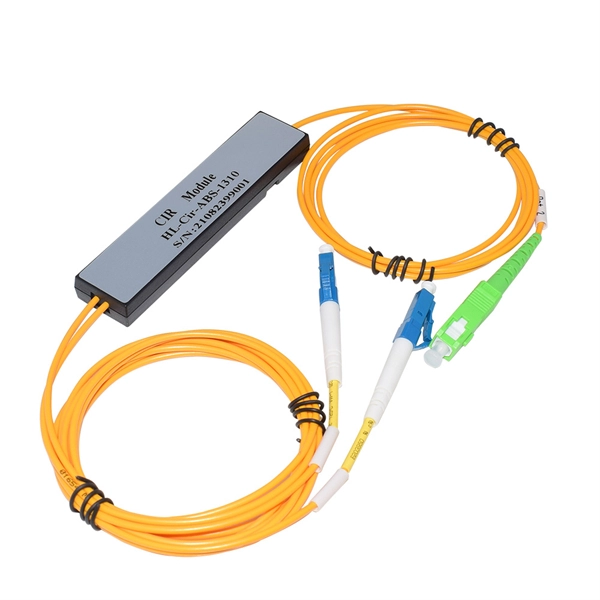
The simplest way to do it is with a fiber media converter on either side. In its basic form, this uses electricity to convert a single Ethernet twisted-pair copper connection to fiber, and back. Running fiber internally involves extending this high-speed link from the service entry point to a centralized location, such as a dedicated media closet or network rack. This DIY effort is undertaken to maximize performance, improve aesthetics, or relocate the Optical Network Terminal (ONT) to a. Proper connection of fiber optic cables is essential to harness these benefits fully, as even minor errors can lead to significant performance issues like signal loss. This article will guide you through the necessary tools, materials, and methods on how to connect fiber optic cables effectively. The process to connect fiber optic cable to router requires careful attention to detail, but I'll walk you through every critical step with the precision and clarity you deserve. In this guide, we'll walk you through how to connect a fiber optic cable to a router safely and efficiently. Why Use Fiber Optic Internet? Before diving into the setup, let's quickly. If you want to run fiber between the two buildings, you can do it on the LAN side of your router for fairly cheap. Instead of waiting for an appointment with a technician or trying to find a time that suits, you can have everything you need for a fast fiber connection shipped to your door, so you can set it up in your own time.
[PDF]
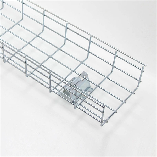
Calculate cable tray fill ratio, weight loading, and derating factors for multi-standard compliance. This calculator features an interactive interface with advanced visualizations. Open the full calculator for the best experience. IEC 61537 covers cable tray and cable ladder systems for the support and accommodation of cables, while NEC Article 392 governs cable. Article Summary: A compliant cable tray installation requires a thorough understanding of NEC Article 392, proper structural support, and precise installation techniques. This guide covers the critical steps, from selecting the right electrical cable tray and performing accurate cable fill. Properly sizing your cable tray is critical for safety and compliance. Follow these simple steps: Define Tray Dimensions: Enter the width and depth of your planned cable tray (in mm or inches). Save your cable tray sizing calculator results as branded PDF. A 12 in ladder tray loaded to 4 in depth has 48 sq in of tray area; with 24 #12 THHN conductors at 0. 0133 sq in each, the screen is about 0. This page is a preliminary cable-tray occupancy screen for early layout work. It adds cable planning area, compares. This publication is intended as a practical guide for the proper and safe* installation of cable ladder systems, cable tray systems, channel support systems and associated supports. Cable ladder systems and cable tray systems shall be manufactured in accordance with BS EN 61537, channel support.
[PDF]

A ladder type cable tray tee is a fitting used to create a branch in a cable tray system, allowing cables to be routed in three directions. Its "T" shape provides a secure and efficient way to split cables from a main tray into two separate paths, ensuring organized and flexible. A cable tray tee and tee cover are components used in cable management systems to support and protect electrical and data cables. Here's a brief explanation of each:. Rigid steel cable tray tee fitting with zero tangent, safety bottom, and full accessory support. ventilation to heat producing cable such as power communication and other with the same or different width of the cable run. All fittings are available in sizes and types corresponding to the straight cable tray sections. These fitting are including: elbow, horizontal cross, vertical inside. NOTE : Equal or un equal tees can be supplied. When ordering state widths W1xW2xW3.. Office: 147/22 Nguyen Sy Sach Street, 15 Ward, Tân Binh Dist, HCMC,VN. Is it possible to connect 2 cabletrays with a "branch piece (left picture)" instead of a "tee (right picture)". The tee has 3 connectors, the branch piece only has 1 connector. I would like to ajust the "Type properties -> Fittings -> Tee" with the branch family, but can't get it accomplished.
[PDF]

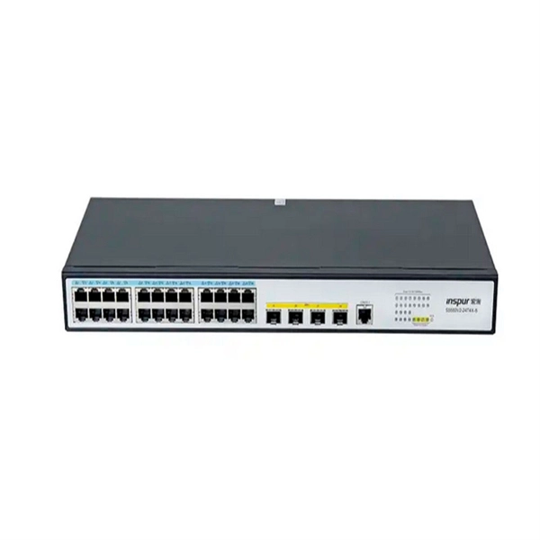
This comprehensive guide will explore the importance and benefits of this integration, provide an understanding of fiber optic cable and Ethernet ports, discuss their compatibility, and offer a step-by-step process for connecting them. Proper connection of fiber optic cables is essential to harness these benefits fully, as even minor errors can lead to significant performance issues like signal loss. This article will guide you through the necessary tools, materials, and methods on how to connect fiber optic cables effectively. Using an optical cable involves connecting it to the right equipment, ensuring proper installation, and testing the system for optimal performance. Here's a step-by-step guide on how to use optical cable effectively: 1. Check Compatibility of Equipment Ensure that your equipment (e., network. One powerful solution to achieve these goals is by connecting fiber optic cables with Ethernet ports. This comprehensive guide combines industry standards with field-tested practices to ensure you achieve a rock-solid. These transceiver modules are hot-swappable input/output (I/O) devices that plug into 100BASE, 1000BASE and 10GBASE ports (for SFP+), which connect the module port with the fiber-optic or copper network. The SFP transceiver modules are hot-pluggable I/O devices that plug into module sockets. The number one cause of signal loss in optical fiber installations is dirt on.
[PDF]
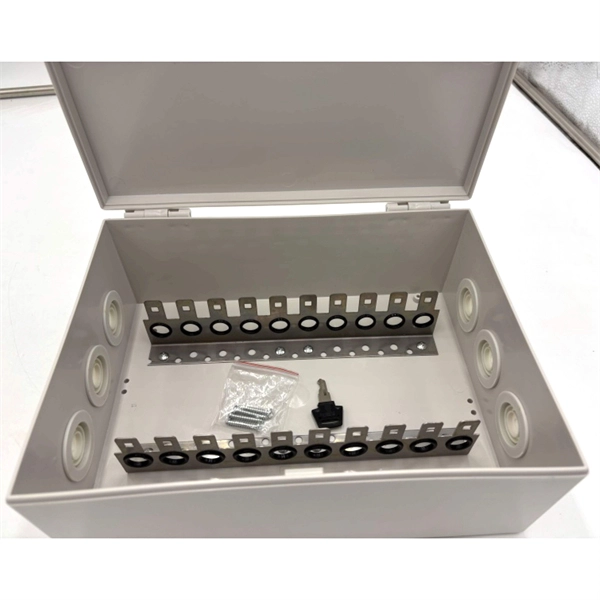
Start by examining the plastic cover closely to identify any tabs or locking mechanisms that may be holding it in place. This robust enclosure houses either the main service disconnect or a sub-panel, acting as a control point for electricity distribution to the property or a dedicated outdoor system like a pool or workshop. Gaining access to the panel's interior is usually necessary for simple tasks like resetting a. Opening electrical boxes outside can be a tricky endeavor. Without the proper tools, knowledge, and safety measures, it can also be dangerous. However, with a few simple steps, you can open an outdoor electrical box safely and efficiently. This is how you can open them to have access to the plug-ins. Once you've loosened the. This guide will explore the steps and considerations for safely and effectively punching out a plastic electrical box. Ensure the wires are not powered before starting work. Flat-head screwdriver, electrical pliers, hammer, and a suitable meter or tester. Locate. Before you attempt to open an outdoor breaker box, it's crucial to prioritize your safety. Here is a set of guidelines to ensure you undertake this task without any hazards: Confirm power is disconnected to the unit by turning off the main breaker or disconnecting the main fuse.
[PDF]
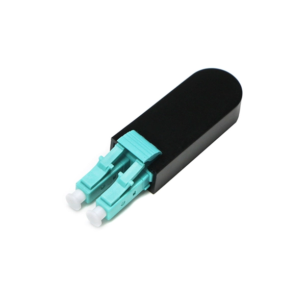
Fiber optic cables often follow a color-coding system to indicate their type: Single-mode fibers - Typically yellow. Multi-mode fibers (OM1 & OM2) - Usually orange or sometimes gray. Choosing the right type of fiber optic cable is essential for reliable and cost-effective network performance. The two main types — Single Mode (SM) and Multimode (MM) — differ in construction, performance, and application. This guide explains how to identify them by appearance, labeling, and. When figuring out if a fiber cable is single mode, one must know the different classifications. Essentially, fiber optics are mainly categorized as: Single Mode Fiber (SMF): This type features a small core and uses laser technology to send a single light mode. Single mode fibers are used for. Knowing how to tell the difference between single mode and multimode fiber is crucial for network efficiency; the core distinction lies in the fiber's core diameter and how light travels through it, affecting bandwidth, distance, and cost. This allows for a single mode of light to travel through the core. With clear tables and updated details, it serves as a comprehensive reference for technicians handling modern fiber optic installations. We'll cover single mode, multimode, and armored fiber cables below. This small diameter core, typically around 9 microns in diameter, allows only one.
[PDF]
Attach a ground wire from one of the threaded studs (A) at the bottom of the housing, to the mounting plate (B). The ground resistance between all system parts shall be <. The protective grounding system, which includes conductor grounds and worker bonding, must be engineered to protect workers from hazardous voltages that can be created by line reenergizing, lightning, or induced oltage. If more than one crew is working independently on the same deenergized line or. Power from factory ground must be installed by a qualified electrician. Each DISTRIBUTION BOX and controller must be grounded. On the US market, a 5. 26 mm 2 (10 AWG) ground wire must be used, and in all other markets a 6 mm 2 must be used. The neutral conductor is typically the grounded conductor connected to the system's neutral point, carrying current under normal operation. Grounding electrode conductors must be connected at. The correct connection method of Distribution box grounding wire mainly includes the following steps: 1. Whether you're a seasoned pro or just starting out, this comprehensive guide will give you practical. This technical article covers protective grounding requirements for steel tower and wood pole supported transmission and distribution lines, and insulated power cables. Protective grounds must be installed so all phases of lines or cable are visibly and effectively bonded together in a multi-phase.
[PDF]

Arduino-Powered Data Transmission with Fiber Optics Welcome to our video tutorial on optical communication with Arduino, designed to be easy t. more. They consist of a transmitter on one end of a fiber and a receiver on the other end. Most systems use a "transceiver" which includes both transmission and. I'm going to use HFBR 1414 fiber optic transmitter module which is manufactured by Broadcom. It is a low-cost high-power transmitter that is designed for use in industrial power generation, power distribution, medical transportation and gaming applications. Internally, the optical fiber consists of a highly reflective central core, which acts like a light guide. Media converters are special fiber optic transceivers used to convert from one type of cable (the media) to another, typically from copper cables to fiber optics, although some media converters will convert from one fiber type to another, e. multimode to singlemode. The FOA Guide has a page about. A fiber optic transceiver (also called an optical transceiver) is a compact module that both transmits and receives data signals through optical fibers. It serves a dual purpose — transmitting electrical signals as light pulses and receiving light pulses to convert them back into electrical form.
[PDF]
In part two of the 7-part series on how to wire a switch, I explain and demonstrate how to install the cables into a multi-gang box. The video focuses on steps that will both save time and simplify the process. In this video, we'll walk you through the process of wiring a home distribution box with a detailed connection diagram. Whether you're an electrician or a DIY enthusiast, this guide will help you understand the basics of home electrical distribution. Part of my job as a professional electrician is keeping my work neat and organized. A tidy work box makes it easier to install lights, switches, and outlets, and it helps future electricians to see what's going on inside the. Learn how to install a distribution box safely and correctly. Covers wiring, placement, standards, and expert tips for a compliant setup. A distribution box is the heart of any electrical system. It takes the incoming power and safely distributes it to different circuits throughout your building. If you're looking to install a switch box in your home or office, it's important to understand the process involved and the key steps to follow. And all the switching and protective devices are installed in the. According to NEC (National Electric Code: Article 1 00-Definitions), a Main Panel (also known as Panelboard, load center, breaker box and distribution board etc. ) is a cabinet or cutout box which contains on controlling and protective devices (such as circuit breakers, fuses, switches etc.
[PDF]
Find out the design of robust cable tray installation in pump stations. This manual includes elements such as material choice, cables with heavy loads of the motors, and grounding as a way of providing long-term reliability. This procedure to clear the method of the supply, installations Cable Tray and Trunking System for the project. Delivery and inspection upon arrival of material at site. Installation of the. No description has been added to this video. Enjoy the videos and music you love, upload original content, and share it all with friends, family, and the world on YouTube. Below is the detailed cable tray installation method statement not only for cable tray but also applicable for GI ladder and trunking for indoor and outdoor applications and in service rooms like pump rooms, electrical rooms and plant rooms etc. All materials intended for cable tray, ladder and. Variations of types of armored cables as found by Variable Frequency Drives (VFDs) are much heavier than regular wires. When the tray is too weak, it will bend and may result in dangerous power failure. When electricity is passed through big cables, they become hot. The plastic covering may melt. association representing the major electrical equipment manufac-turers in the U. QA/QC : Quality Assurance / Quality Control Engineer. MIR : Material.
[PDF]
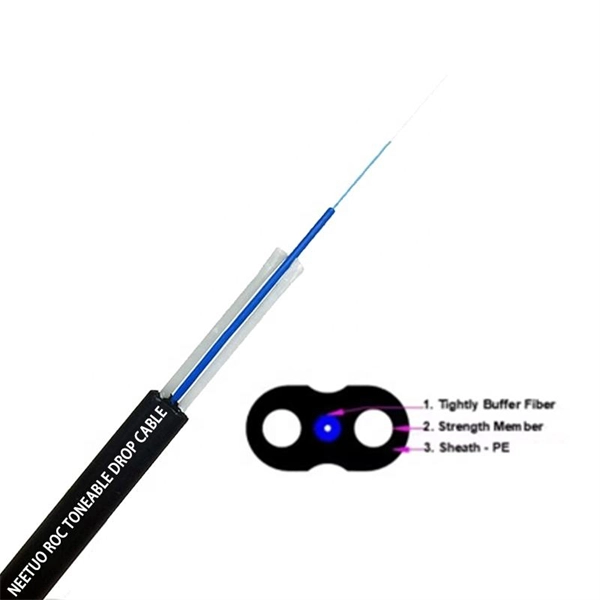
Fiber optic cable installation costs between $1,500 and $7,000 for your home, with prices varying by cable length and installation method. The installation type you choose and the layout of your property determine the total labor and materials needed for your project. How Much Does Fiber Optic Installation Cost Per Foot? Cable Material Costs: Installation Costs by Method: Prices can range from $1 to $50+ per linear foot depending on the method and complexity. The initial cost of installing fiber optic cables can vary depending on the chosen installation method. Home and business fiber optics projects typically range from a few hundred to several thousand dollars, depending on run length, fiber type, and labor needs. This. Whether you're running fiber to a home or a data center, here's exactly what contractors are charging in 2026. What is the real cost of fiber optic cable per foot in 2026? After analyzing 40+ U. fiber projects, we've assembled current material rates, labor burdens, and hidden fees. You should account for permit. If you're grappling with the complexities of budgeting for fiber optic installations 1, understanding the cost dynamics of single-mode fiber optic cables 2 is crucial. The price per foot includes the fiber itself, connectors, and basic installation factors, with main drivers being cable type, distance, and any required conduit or termination hardware. This article outlines cost expectations.
[PDF]
PC configuration software for Reyrolle products including Reydisp Manager 2, Reydisp Manager 1, and Reydisp Evolution. Doble RTS™ (RTS) is the premier protection testing software system for improving the work of testing relays and managing test records. Process consistency with power and flexibility set RTS software apart, and tremendous automation enables unmatched efficiency, accuracy and productivity. Apply your. Download documents, support information, software, video and audio content. IEC61850 Digital Substation Testing With 15 years experience in IEC61850 digital substation testing, KINGSINE portable relay testers are designed for comprehensive testing in both traditional and digital substations, including MU and IEC61850 compliant IEDs. Protection Relay Test Set/Kit KINGSINE. The commissioning of protection systems is an essential step to ensure the safety, reliability, and operational efficiency of electrical installations. In this context, the testing of protection relays and IEDs (Intelligent Electronic Devices) must be carried out with maximum precision, speed, and. A software designed to manage all aspects of protective relay testing using the Megger SMRT and FREJA models of relay testers. Facilitates steamlined and efficient relay protection testing through automation and relay modules. By using one of the over 400 relay templates with relay settings import. Portable at just 15 kg, the FREJA 300 is intended primarily for.
[PDF]
This video shows real on-site footage of electrical installation, demonstrating safe and standardized wiring methods used by professionals. Whether in a home or an industrial facility, this box keeps your electrical setup organized, functional, and efficient. However, the key to a safe and reliable system lies in proper installation. If it's done poorly, you risk short circuits, fire hazards, or system failure. Done right, it ensures. Whether you are an electrical contractor or a construction brigade, knowing how to properly and safely install distribution boxes is the basis of ensuring the safe operation of the entire system. This article details the process of installing them, which helps you comprehend distribution boxes. How to Install a Cable Distribution Box Safely and Correctly? In modern electrical systems, cable distribution boxes (also known as electrical distribution boxes or distribution boxes) play a crucial role as the key hub for managing, distributing, and protecting circuits. Can I convert the circuit wiring in my shop to be used for different equipment? Converting Existing Circuit Wiring in a Workshop or Garage. There is a demand for more RCD protection of final circuits, affect Type B MCB distribution boards and their protective d bar arrangement designed to accept single and/or double pole OCPDs.
[PDF]