
In this guide, I'll walk you through everything you need to know about choosing the right cable trays for your cables. Whether you're dealing with power cables, control cables, or communication cables, I'll break it down step by step. A 50 mm cable tray is used to organize and protect cable routes in industrial, commercial, and infrastructure facilities. This compact solution is suitable for power distribution lines, low-current systems, and engineering communications. Mirankul Group manufactures cable trays in Uzbekistan. Accessories for cable systems include a variety of different components necessary for the proper functioning of cable routes. They provide a structured and secure pathway for cables, ensuring organized installation and easy maintenance. Cable Trays are important for ensuring the protection of the wiring system and supporting insulated electric cables used for distribution and communication. Brilltech Engineers Pvt. Understand Your Cable Tray Requirements Before selecting a cable tray, consider the following key factors:. Selecting cable trays can feel overwhelming, especially with so many options available. But don't worry—I've got you covered.
[PDF]
Here's what to consider: 1. Fiber Type Choose single-mode for long-distance transmission and multimode for shorter runs. Connector Compatibility Match the connector (LC, SC, ST, etc. ) with your equipment ports. Fiber Count Select based on network scale—higher. Executive Summary: A fiber optic pigtail is one of the most commonly specified yet least understood components in structured cabling. Get the wrong connector type, the wrong polish, or skip proper fusion splicing technique—and you're looking at elevated signal loss, increased back reflection, and a. Today, I'll show you how to pick the right patch cord or pigtail — step by step. You plug it into a switch, router, or patch panel. A pigtail is for splicing. You fuse it to a. A fiber pigtail is a single, short, usually tight-buffered fiber optic cable with a factory-installed connector on one end, and un-terminated fiber on the other end. Fiber optic pigtails are used to terminated fiber optic cables via fusion splicing or mechanical splicing as shown in the picture. In this guide, we'll break down what fiber optic pigtails are, how they work, their types, and how to choose the right one for your application. By the end, you will have a comprehensive understanding of why pigtails deserve a place in every fiber deployment toolkit. Each type has its own unique design, size, and compatibility features. Understanding these differences is essential for choosing the right pigtail for your network.
[PDF]
This is the FOA's Online Guide To Fiber Optics, Fiber Broadband & Premises Cabling. With 19+ years of experience installing fiber-optic cables at over 20,000 locations, we've seen how prices vary based on cable type, project scope, and installation complexity. Fiber-optic cable materials typically cost $1 to $6 per linear foot, depending on fiber count and cable type. Main cost drivers include cable grade (indoor vs outdoor, armoured), distance, and labor for trenching, splicing, and termination. This guide presents ranges in USD and practical price estimates to help. Fiber optic cables are essential components in today's broadband, FTTx, and data center networks. Whether you're planning a national fiber rollout or sourcing cables for enterprise infrastructure, understanding how fiber optic cable pricing works can help you budget more effectively and make better. We have included Per Foot conversions for reference (1 Meter ≈ 3. Best For. * Disclaimer: Prices fluctuate based on raw material indices (Glass/Copper/Polymer) and cable core count (e. These cables, constructed with glass or plastic fibers, transmit data through light pulses, offering.
[PDF]

In this post, we'll walk you through practical tips, essential tools, common pitfalls, and the techniques that will help you get your fibre patch cable installations right the first time. Correct patch-cord installation is essential for maintaining low insertion loss, stable return loss, and long-term reliability in both indoor and outdoor fiber networks. Proper handling, routing, cleaning, bend-radius management, and connector alignment ensure that the optical link meets design. Proper connection of fiber optic cables is essential to harness these benefits fully, as even minor errors can lead to significant performance issues like signal loss. This guide addresses expert-certified best practices applied by professionals in the telecommunications, data. Yingda outlines the tools and materials needed to install fiber optic patch cords, as well as a complete step-by-step installation guide and important safety considerations to take. We will also tie this procedure back to the earlier discussion of multi-mode fiber types (OM1 to OM5) and connection. The Flex-Angle boot is designed to bend any angle or direction from straight to 90°. OMC flex angle boots for LC&SC fiber optic connectors are available on any single-mode or multimode patch cord. They are designed so the installer can pre-bend the boot into any direction or angle. Selecting the correct fibre patch lead is crucial for optimising signal performance and.
[PDF]

Cable Trays* — Max two 24 in. (610 mm) wide by max 6 in. (151 mm) deep open-ladder cable tray with channel-shaped side rails formed of 0. 54 mm) thick aluminum or min 0. In practice, cable tray dimensions are a system of interrelated measurements —width, depth, length, and material thickness—that directly affect cable fill compliance, heat dissipation, structural loading, and long-term expandability. From an engineering standpoint, cable tray dimensions are not. Perforated Cable Tray System expertly constructed from high-grade stainless steel, offering exceptional durability and resistance to corrosion. With side height 100mm. A properly designed and installed cable tray system will provide. Studs — Wall framing to consist of wood studs or channel shaped steel studs. Wood studs to consist of nom 2 by 4 in. Additional studs shall be used to completely frame. Best Size: Here, deep trays (75mm to 150mm) are used since power cables are typically thick and heavy. Data cables, such as your Wi-Fi or computer ones, are extremely sensitive. They do not get hot; however, they do not like to hang or sag. In case a data cable folds in an excessive manner, the. ect the minimum bend ra-dius for cables as they exit the bottom of the cable tray. A rung spacing of 6 to 9 inches (150 to 230 mm) is preferable when the cable tray cont d for instrumentation and control applications that require additional protec eferred to support and protect numerous small.
[PDF]

This article helps network engineers, field techs, and IT managers choose the right single-mode transceiver campus optics by tying IEEE Ethernet requirements to day-to-day deployment constraints: reach, budgets, DOM behavior, and operational limits. Huawei eKit offers a comprehensive series of pluggable optical modules in the Huawei eKit portfolio. The wide variety of modules gives you flexible and plug-and-play options for all types of interfaces. You will also get a practical checklist, common. Multimode and Singlemode optical modules differ in terms of fiber type, transmission distance, cost, and application scenarios. Understanding these differences is the first step in selecting the right module. This saves space and money. Dual fiber modules use two fibers. They are easier to set up and give steady communication. Its primary function entails converting electrical signals into optical signals. This assembly comprises a light source, such as a laser diode or a semiconductor light-emitting diode (LED), an optical interface, a. A single-mode receiver is an optical device that converts incoming light signals—carried over single-mode fiber (SMF)—back into electrical data. Unlike multimode receivers, which accept wider light beams from LEDs or VCSELs, single-mode receivers pair exclusively with laser-based transmitters.
[PDF]

Optical modules (also known as fiber optic transceivers) are essential components in modern communication networks, enabling high-speed data transmission by converting electrical signals into optical signals and vice versa. Among various optical module form factors, SFP (Small Form-Factor Pluggable). A fiber optic transceiver (also called an optical transceiver) is a compact module that both transmits and receives data signals through optical fibers. It serves a dual purpose — transmitting electrical signals as light pulses and receiving light pulses to convert them back into electrical form. An optical module usually consists of an optical transmitting device (TOSA, including a laser), an optical receiving device (ROSA, including a photodetector), functional circuits,main control circuit board (PCBA), housing and optical (electrical) interface and other components. How do optical. At the heart of fiber optic technology lies a crucial component: the optical transceiver. Let's explore the key aspects of optical transceivers to help you navigate.
[PDF]

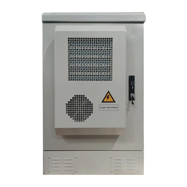
In this video, we'll walk you through the process of wiring a home distribution box with a detailed connection diagram. Whether you're an electrician or a DIY enthusiast, this guide will help you understand the basics of home electrical distribution. more Welcome to our channel! In this video. Single Phase wiring installation is the most common wiring in residential buildings. In Single Phase supply (230V in UK, EU and 120V & 240V in the US & Canada), there are two (one is Line (aka Phase, Hot or Live) and the other one is Neutral) incoming cables from the utility poles to the kWh energy. A distribution board or distribution box is where the main power supply is distributed to multiple loads. And all the switching and protective devices are installed in the distribution box. Single Phase Distribution Box generally consists of Double Pole MCBs, Single Pole MCBs, and RCCBs. An electrical panel box, also known as a breaker box or a distribution board, is a crucial component of any electrical system. It serves as a central hub for distributing electricity throughout a building, ensuring that power is delivered safely and efficiently to all the required locations. What is Distribution Board? Distribution board.
[PDF]

Given the access to a fusion splicer, you can splice the pigtail right onto the cable in a minute or less, which greatly speeds the splicing and saves significant time and cost spent on field termination. A fiber optic pigtail is a short length of optical fiber cable with a factory-terminated connector on one end and a bare, exposed fiber on the other. Unlike a patch cord—which has connectors on both ends—the bare fiber end of a pigtail is designed to be permanently spliced (either by fusion or. The Contractor tasked to perform testing or splicing on any fiber optic cable will follow these testing standards to fulfill their contractual obligations. The Contractor must utilize the correct equipment and testing techniques to gain acceptance, or the work cannot be approved. While for mechanical fiber optic pigtail splicing, it precisely holds a fiber optic pigtail. Fiber optic fusion splicing is on the rise and Corning's Pigtailed Splice Cassettes enable faster field splicing and easy modular management of connectorization within the housing. Pre-routed and preloaded, pigtailed splice cassettes reduce installation time by up to 40%. Today, fusion splicing. Next, we will introduce three common types: SC, FC, ST fiber optic pigtails. 5mm pre-radiused ferrule which is made of zirconia or stainless alloy.
[PDF]
Spring knot is used to connect cable tray or trunking to channel. Approved and correct fittings are used. Bonding jumper is installed. Tagging/labelling is provided. Installed containments are free of damages. The purpose of this article is to define the sequence and methodology for the installation of electrical cable trays, cable trunking, cable raceways and boxes, junction and pull boxes. These guidelines are not intended to cover all details or variations in cable ladder and cable tray. Hubbell's NEXTFRAME® Ladder Tray is the effective and widely used cable runway that supports and delivers bundles of cable between cabinets, racks, and closets, along walls, and suspended from ceilings. The Ladder Tray features light, rugged, tubular steel construction. It is designed for. bow fittings, etc. ) Of the tray being mounted. Supports should provide strength and working load sufficient to the load require ents of the cable tray system being supported. Structural building members should never be cut, and cable trays should not be installed in hoist ways or where subject to. Welcome to our comprehensive guide on installing wall brackets for different types of cable trays and cable ladders! In this video, we will walk you through the installation process for four different types of wall brackets, specifically designed for cable trays, mesh cable trays, and cable.
[PDF]

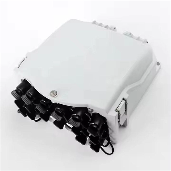
The compact 1 port ftth fiber termination box can hold 2 cores splicing, termination and coil up to 30 meters long for cable management in FTTH network. The 1 port fiber termination box is available for fiber optic cable coiling, it is great to connect optical cable and pigtail and protect fiber splices from damage. It is small, lightweight, and offers the function of fiber splicing, storage, and termination, mainly used in residential buildings. The maximum distance for single mode fiber optic cable can extend up to several hundred kilometers, making it ideal for long distance data transmission. One type of single mode fiber is known as “G. 652,” which is commonly used in telecommunications networks. Here are some general guidelines: 1. The shorter distance accounts for the. A fiber optic distribution box (FDB) is a protective enclosure for managing fiber optic cables. It organizes connections, splices fibers, and distributes signals in networks like FTTH (Fiber-to-the-Home) or FTTB (Fiber-to-the-Building). It acts as a central point for terminating, splicing, and distributing these cables, providing necessary protection and. The Fiber Optic Association, Inc. (FOA) was founded in 1995 to help develop the workforce to build the fiber optic networks to support a rapid expansion in communications and the Internet. The charter of the FOA was to promote professionalism in fiber optics through education, certification, and.
[PDF]

Check the electrical load and ensure that the sensors do not exceed the 10 Amp maximum. Check each wire for damage that may lead to a short. Check the tightness of electrical connections along the power. Issue: Frequent tripping of circuit breakers is one of the most common issues in distribution boards. It can occur due to overloaded circuits, short circuits, or ground faults. Solution: Identify the Cause: Check if the breaker is tripping due to overloading. Internal Inspection Open the distribution box and check for dust and debris accumulation. Inspect circuit breakers for proper operation. Ensure all connections are tight and secure. Each circuit breaker protects a specific circuit in your home, preventing excessive current from damaging wiring and. MDB is panel under power distribution system which consists of a fuse, circuit breakers and ground leakage protection units. Where electrical energy is taken from a transformer or an upstream panel to distribute electrical power to numerous individual circuits or consumer points. Various types of panels exist in every electrical.
[PDF]

Step-by-step guide on connecting an inverter to your distribution board for uninterrupted power supply. The process begins with turning off the main power supply to ensure safety. Next, choose an inverter with a suitable capacity to handle your power needs, ensuring it matches the. In this article, you will find information about connecting inverter to distribution box: essential safety tips, step-by-step guidance, and common mistakes that often lead to inverter failure, so that you can avoid them. Last Updated on September 17, 2025 by June The most extensive use of inverter. Connecting an inverter to a distribution board allows you to harness stored energy from batteries or solar panels for powering electrical devices in your home. This setup provides backup power during outages and can also contribute to energy savings by utilizing renewable energy sources. This guide. In this video, we'll guide you through the process of wiring a UPS (Uninterruptible Power Supply) or inverter for your home or office. By following a few simple steps, you can easily learn how to connect an inverter DB wiring diagram. Connecting an inverter DB wiring. Scroll to the bottom of any page to find a sun or moon icon to turn dark mode on or off! I'm not an electrician and do not want to screw this up. What type of wiring do I need to connect the inverter to the distribution box? I have a 1*60A 4*20A FL+LS distribution box with a Sungold Power 5000W 48V.
[PDF]
This article will provide an in-depth analysis of outdoor cable types, key selection criteria, core installation steps, critical precautions, as well as subsequent testing and maintenance guidelines, helping you build a robust and durable outdoor optical communication link. Therefore, understanding the characteristics of outdoor fiber optic cables and mastering proper installation methods is crucial. Plan your outdoor fiber installation carefully by surveying the site, choosing the right cable type, and following FOA and OSP standards to ensure reliability. In this video, we'll walk you through the process of establishing a robust outdoor fiber connectivity solution. Follow our guide and establish a r. more Welcome to. Running a cable through an exterior wall can be a daunting task for many homeowners, but with the right tools and techniques, it can be done efficiently and safely. With the increasing demand for high-speed internet and reliable networking, it's essential to know how to properly install CAT 6 cables outdoors. In this article, we'll take you.
[PDF]

While optical power meters are the primary power measurement instrument, optical loss test sets (OLTSs) and optical time domain reflectometers (OTDRs) also measure power in testing loss. TIA standard test FOTP-95 covers the measurement of optical power. This measurement is the basis for loss measurements as well as the power from a source or presented at a receiver. Typically both transmitters and receivers have receptacles for fiber optic connectors, so measuring the. You need a power meter to measure power in a fiber optic system; most power meters come with a screw-on-adapter that matches the connector being tested and a little aid from the network electronics to turn on the transmitter. During the measurement of power, the meter must be set to the proper. Fluke Networks sets the standard in network testing with its advanced range of fiber optic power meters and fault locators, designed to ensure the highest precision in fiber optic meter readings and power evaluations. This is measured in decibels (dB). Splitters, fusion splices, connectors and. To use a power meter for fiber optic testing, always clean connectors first with lint-free wipes or click-to-clean tools. Select the correct wavelength and set your reference. Consistent procedures ensure accuracy.
[PDF]