
Arduino Safety Relay Box With Wall Socket : A relay is an electrically operated switch. In this project there is no real need to isolate one circuit. Relay rooms are essential in modern commercial or industrial buildings, serving as secure enclosures for electrical relays that manage power distribution and automation systems. Designing a relay room requires balancing technical precision with safety, efficiency, and future scalability. Many relays use an electromagnet to mechanically operate the switch and provide electrical isolation between two circuits. In this article, you will learn how to design an electrical control cabinet for optimal safety and efficiency, following some. This handbook covers the code of practice in protection circuitry including standard lead and device numbers, mode of connections at terminal strips, colour codes in multicore cables, dos and donts in execution. Reliable components ensure system faultlessness and durability. Modern design and user-friendliness. equipment of most. This is Part 1 in a series of tutorials that will show you how to build a Bussmann RTMR fuse/relay block. If you're not familiar with this product, it's a simple waterproof enclosure that allows you to connect accessories on your vehicle through relays and/or fuses. After reading this tutorial, you.
[PDF]

This certification requires completion of the following two courses, which may be completed in any order within an 18-month period: National Electrical Code 2020, 4 days, 2. 8 CEUs, which you can take In-Person or Virtual, Live. Electrical Safety for Inspectors, 4 days, 2. After completion of all requirements you must submit your certification application. Your certification package will include a certificate and laminated wallet card. {{$pageCtrl. description}}. General requirements for certification include passing an exam or exams, specific industry related experience, successful performance of key role specific activities, and personal recommendations (Levels III and IV). Once earned, certification must be maintained through Continuing Professional. Whether you specialize in fire protection systems, building and life safety, or electrical, our acclaimed certification programs can help verify your competence and set you apart from your peers. Empowering employees to work safely and effectively with Megger's offering of courses and certification programs in electrical maintenance, electrical safety, as well as through our custom-tailored training. Copyright © 2026 Megger, all rights reserved. Participants gain practical experience with real-world equipment, learning to interpret.
[PDF]

This article helps network engineers, field techs, and IT managers choose the right single-mode transceiver campus optics by tying IEEE Ethernet requirements to day-to-day deployment constraints: reach, budgets, DOM behavior, and operational limits. Huawei eKit offers a comprehensive series of pluggable optical modules in the Huawei eKit portfolio. The wide variety of modules gives you flexible and plug-and-play options for all types of interfaces. You will also get a practical checklist, common. Multimode and Singlemode optical modules differ in terms of fiber type, transmission distance, cost, and application scenarios. Understanding these differences is the first step in selecting the right module. This saves space and money. Dual fiber modules use two fibers. They are easier to set up and give steady communication. Its primary function entails converting electrical signals into optical signals. This assembly comprises a light source, such as a laser diode or a semiconductor light-emitting diode (LED), an optical interface, a. A single-mode receiver is an optical device that converts incoming light signals—carried over single-mode fiber (SMF)—back into electrical data. Unlike multimode receivers, which accept wider light beams from LEDs or VCSELs, single-mode receivers pair exclusively with laser-based transmitters.
[PDF]
The global protective relay market size was worth more than USD 2. 82 billion in 2025 and is poised to witness a CAGR of over 5. 5%, crossing USD 4. 82 billion revenue by 2035, fueled by rising integration of digitalization & IoT in protective relay. The global market for Protection Relays was valued at US$ million in the year 2024 and is projected to reach a revised size of US$ million by 2031, growing at a CAGR of %during the forecast period. A protection relay is a smart device that receives inputs, compares them to set points, and provides. The Protective Relay Market was valued at USD 3. 9% through 2024 to 2030, reaching nearly USD 3. 4%, according to Strategic Market Research. Protective relays are essential components of modern power systems. The Protection Relays Market encompasses the design, manufacturing, and deployment of electromechanical, solid-state, and digital relays that monitor electrical systems for faults or abnormal conditions and initiate protective actions.
[PDF]
In most cases, you just need to enter the router's IP address into a web browser and then log in with the default admin username and password. For some routers, you can log in with a mobile app. To set up your wireless network, begin by signing in to your GFiber account and navigating to your router's device configuration. Find your appointment using your order ID or internet account number. Check your bill, set up AutoPay, or make a payment. Get AutoPay Select one of our internet-related topics to troubleshoot the issue. We'll. Forgot email? Not your computer? Use a private browsing window to sign in. Learn more about using Guest mode. Ensure you have an active connection (wired or wireless) between the router and the device you're using to access the admin page. If the Wi-Fi connection has been previously disabled through the admin page, you may not be able to enable it after a Factory Reset is completed. Establish a Wi-Fi or. The default router IP for AT&T is usually either 192. 1, depending on the gateway model. Once you've entered the default ATT router login IP, you'll gain access to the. Whether you got your router from your ISP or purchased it yourself, logging in to your router is simple.
[PDF]
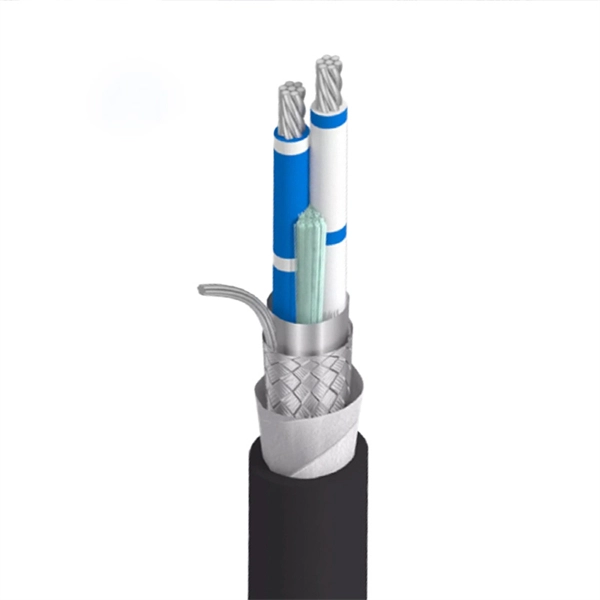
A cable tray system supports and protects both power and signal cables and facilitates upgrading, expanding, reconfiguring, or relocating networks. Most of these systems are open, allowing efficient heat dissipation and easy access for replacement and repairs. This is the role of the cable tray system—a structured framework designed to support and organize insulated electrical cables, control cables, and communication lines. Far superior to traditional conduit in many applications, cable tray systems offer unparalleled accessibility for maintenance. In this guide, we explain what cable trays are, the main types available, how to choose the correct size and duty rating, and what to consider when designing a cable tray installation. There are several types of cable trays, including ladder, perforated, solid bottom, basket, and channel trays. Each cable tray type performs a different function and comes in various materials such as aluminum. Cable trays are components of support systems for power and communications cables and wires. They provide a safe and reliable way to manage the complex network of cables that run throughout buildings, data. Industrial electric cable trays, are fundamental to ensuring a safe and organized installation of electrical systems. These support systems are used to organize electrical cables inside industrial, commercial, and residential buildings and play an important role in making sure cables are protected.
[PDF]

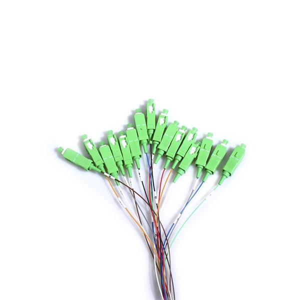
How to Terminate a Multi-mode Fiber Optic Cable with LC mechanical fast connectors. Fusion Splicer: For joining two fibers permanently by fusing them. Safety Equipment: Gloves and safety glasses are crucial to protect against the tiny glass shards of fiber optics. Adhere to industry standards such as. Here are the detailed epoxy LC connector assembly and termination instructions for both single mode and multimode LC connectors. The steps are pretty generic and are applicable to most major brands' LC connectors on the market, such as those from 3M, Seiko, Corning, Molex, AMP, etc. Here are the LC. We terminate fiber optic cable two ways - with connectors that can mate two fibers to create a temporary joint and/or connect the fiber to a piece of network gear or with splices which create a permanent joint between the two fibers. Inject glue Use special glue, insert the glue bottle from the tail handle, squeeze the glue bottle until glue overflows from the end of the ceramic ferrule. Remove the glue bottle and set the connector aside for later use. LC Multimode & Singlemode Connector Termination Instructions Put on safety glasses and prepare work area by organizing all necessary tools from the Fiber Termination Kit (P/N: FTERM-L2), LC Upgrade Kit (P/N: FTERM-LC) and the Consumables Kit (P/N: FT-CKIT-L2). Place primer bottle into primer stand.
[PDF]
This guide demystifies fiber optic splitters, explaining their design, operating principles, types, key specifications, and real-world applications. Whether you're a network engineer designing a PON (Passive Optical Network) or a homeowner curious about how your fiber connection works. I'm planning to use a TP-Link MC220L transceiver to convert the optical signal to ethernet. This ethernet will then go through a 1 Gbit/s switch, and rout two ethernet cables to each floor. On each floor each ethernet cable will be connected to a router, which will then distribute the internet. DWDM/CWDM is like a two-edged sword. For a small fee (the procurement of the modules and the circulator) you can split/splice one physical fibre optic cable into multiple pairs. The downside is that once you loose your one-and-only fibre link (to a cable-hunting-buck-hoe) then you're in trouble. Fiber optic splitters enable the division of optical signals into multiple paths, allowing information to be distributed to multiple subscribers or devices simultaneously. Understanding the inner workings of fiber optic splitters is crucial for network administrators, technicians, and anyone. The answer is yes, and it's a practice widely used in the industry to distribute signals to multiple destinations without degrading the signal quality significantly. What is Fiber Line.
[PDF]

In order to help, we put together a short list to help you at least figure out how much a “class” of laser diode might cost. This list is a rough guide of pricing by package style and output power for 808, 915, 940, 980nm devices. Semiconductor laser diodes range widely in price based on a few key parameters. The wavelength, power, spectral qualities, package type, cavity type and quantity will all have an effect on the price. You can buy a laser diode for less than a dollar. But the price can also be in the tens of. Creality Falcon A1 10W Laser Engraver Enclosed Laser Cutter for Wood Metal ect. Get the best deals for 100W Laser Diodes at eBay. We have a great online selection at the lowest prices with Fast & Free shipping on many items!. Check each product page for other buying options. Need help? Discover powerful 100W laser engravers and cutters for wood, acrylic, leather, and more. Find precision machines for professional and DIY projects. A 100-watt laser diode represents a high-power semiconductor device capable of producing intense, coherent light used across industrial, medical, telecommunications, and defense applications. These diodes vary significantly in design and beam characteristics, allowing engineers to select the. DIY CNC Upgrade Module & Kit 100W MULTICOLOR 100watt Eliminator E-143 Asteroid Stage Lights. Light Move With Music Professional Laser Diode Hyperpigmentation System with Treatment Gel Kit. With power ranges.
[PDF]

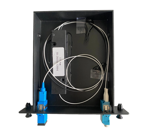
The maximum split ratio of the FBT splitter is as high as 1:32, which means that one or two inputs can be divided into outputs of up to 32 optical fibers. By dividing a single optical signal from a central Optical Line Terminal (OLT) into multiple outputs for Optical Network. In this guide, you'll learn how fiber splitters function in PON networks, the difference between PLC and FBT types, and how to choose the best model for your rollout in 2025. What Are Fiber Optic Splitters in PON? Fiber splitters are passive devices that divide one optical input signal into. FTTH relies on Passive Optical Network architecture, which enables one fiber leaving the central office to serve multiple subscribers through optical splitting. This structure eliminates the need for powered elements in the distribution segment, reducing operational costs while ensuring high. Optical splitter is an integrated waveguide optical power distribution device that serves to split optical signals. It is widely used in passive optical networks (such as EPON, GPON, BPON, FTTX, FTTH, etc. ) and plays an important role. When an optical signal is transmitted in a single-mode fiber. The FTTH network serves as the infrastructure enabling data transmission in the form of light signals over optical fiber from the operator's switching equipment directly to a home or business. Accurately understanding the principles, differences, and applicable boundaries of.
[PDF]

Product Range: PLC splitters, FBT splitters, fiber optic adapters, patch cords Price Range: $5 to $150 depending on splitter ratio and specs Overview: TTI Fiber is a global supplier known for quality optical components. FBT (Fused Biconical Taper) Fiber Optic Splitters. These devices splits the fiber optic signal from a single Input to two Outputs. Available in 50/50, 30/70, and 90/10 spit ratios. A fiber optic splitter is different from WDM. WDM can divide the. FBT (Fused Biconic Taper) Coupler Splitter is a commonly used fiber optic coupler and splitter for distributing optical signals to multiple output channels. FBT splitters are reliable and cost-effective, typically used for smaller split ratios like 1x2 or 1x4. The physical packaging or form factor of a splitter is crucial. FBT Coupler Splitters is widely accepted and used in passive optical networks, especially for instances where the split configuration is smaller (1×2, 1×4, etc. FBT is the traditional technology in which two fibers are placed closely together, typically twisted around each other and fused. FBT Fiber Splitter, also known as a fiber optical coupler, separates fiber optic light into many portions using a predetermined ratio. Unlike PLC splitters, FBT splitters employ distinct splitting methods and may be constructed using singlemode, multimode 62. 5, or multimode 50 fibers.
[PDF]
How to de-pin/re-pin automotive connectors in 7 easy steps like a pigtail expert. Find the right tools, remove the front cap, release the catch, release and pull, insert the terminal/pin. Video tutorial available. Save money on truck repairs by repurposing a damaged pigtail. Learn step-by-step how to rewire and secure your connector for reliable lights on the road. This comprehensive guide covers the essential practices that separate professional. Whether you utilize the depin/repin method or choose to solder and shrinkwrap your repair, having the right connector repair tools is vital. We have most of the ones you need, here. At a fraction of the price of the name-known brands but at the high quality you expect these connector, wire repair. Choose TPI [engine type] from the link provided and you will find the pigtails you need. Personally (to save $50), I'd probably dig into the harness cut/splice to switch as needed. You COULD install. Short answer: An automotive wiring pigtail is a short section of wire with a pre-attached connector that lets you repair or replace a damaged plug without replacing the entire harness. It provides a plug-and-play repair solution that restores OEM fit, seal, and electrical reliability. Pigtails are. Nissan Maxima Harness Wire Connectors, How to find them & Where to buy them.
[PDF]
Find out VCSEL's definition, working principle, benefits, limitations, and applications. The vertical-cavity surface-emitting laser (VCSEL / ˈvɪksəl /) is a type of semiconductor laser diode with laser beam emission perpendicular from the top surface, contrary to conventional edge-emitting semiconductor lasers (also called in-plane lasers) which emit from surfaces formed by cleaving. A vertical cavity surface emitting laser, comprising: light-emitting units (20) arranged in an array, wherein the light-emitting units arranged in an array are located on a surface of a substrate (10); a first passivation layer (40), the first passivation layer (40) being located on the surfaces. A specific photonics technology that shows great promise for high speed intra-satellite data transfer applications is the Vertical Cavity Surface Emitting Laser diode (VCSEL). It is a semiconductor device with light emission perpendicular to the chip surface. The resonator (cavity) is realized with two semiconductor. Two-dimensional arrays of vertical-cavity-surface-emitting laser diodes (VCSELs) have been fabricated by an ion-milling etching-technique. The etching of large-area VCSEL-arrays has been successfully demonstrated.
[PDF]

An Optical Splitter, also known as a beam splitter, is a passive optical device that divides a single input optical signal into two or more output signals. Conversely, it can also combine multiple signals into one. Knowing the difference between a splitter and an optical coupler helps you build better networks. You make your network work better when you pick the right device for each job. You can connect many users to one port with 1:n or 2:n splitters. By dividing a single optical signal from a central Optical Line Terminal (OLT) into multiple outputs for Optical Network Terminals (ONTs) at users' homes, splitters eliminate the need for dedicated fibers to each residence—slashing infrastructure costs while scaling network reach. This guide. In a Passive Optical Network (PON), a single optical fiber carries massive amounts of data using light. Signal Input: The fiber splitter receives the optical signal from the upstream network node and enters the splitter through the input fiber. Signal Distribution: Inside the splitter, according to the design structure and different. Splitters are passive optical devices that divide or combine optical signals, and they come in various types, including power splitters, uneven splitters, and wavelength-division multiplexing (WDM) splitters. Each type serves specific applications, enabling efficient use of optical infrastructure.
[PDF]

The modern electric power transmission, control, and distribution network demands precision, reliability, and advanced data analytics for each step in its operation. As a Relay Protection Engineer, your work in relay testing and commissioning is critical to ensuring system safety and continuity. In. The testing and verification of protection devices and arrangements introduces a number of issues. This happens because the main function of protection devices is related to operation under fault conditions so these devices cannot be tested under normal operating conditions. Protection relays are critical for detecting faults, initiating protective actions, and isolating faulty sections of the. Relay systems protect high-voltage equipment and transmission lines to ensure safe, stable systems. Although failure of a protective relay system may have severe local or regional impacts, most protective relay systems are not required to operate to prove they are in working order. Ensuring that. The strategies available to remove these risks are many, but all involve some kind of testing at site. Modern power systems are becoming increasingly complex, with growing demand, integration of renewable energy, and rising expectations for reliability and safety. In this environment, protection relays serve as the guardians of.
[PDF]
