Join Jake from Omnitron in this comprehensive tutorial. Understand the nuances of single-mode and multimode fibers, and how to bridge the gap using media converters. Enhance your tech knowledge and. But what happens when you need to connect an existing multi-mode campus network to a new single-mode service provider link? You can't just splice them together. This is where fiber conversion comes in. This guide will break down the professional methods to achieve seamless single-mode to multi-mode. Single-mode (SMF) and multi-mode fiber (MMF) use different core sizes, sources and wavelengths. These differences determine which transceivers work with which fiber and how far signals can travel. Let's analyze the differences between multimode and single-mode fiber to understand why networks require fiber mode conversion and. How can we convert the multimode to a singlemode fiber system? This complete guide will provide answers to these questions. That is because SMF and MMF have. There are two main types of fiber optic cables: single mode and multimode. Although they can do the same job in some instances, the different construction methods make each of them better suited to certain tasks and budgets. What if end B is located in another building, dozens of kilometers far away from end A? Or end B equipment is single-mode or must use a single-mode fiber connection? In the former case, you.
[PDF]

You can't directly connect a fiber optic cable to your router. You need an intermediary device. The key component is an Optical Network Terminal (ONT) or Optical Network Unit (ONU). Why Use Fiber Optic Internet? Before diving into the setup, let's quickly recap why fiber optics are worth the effort: Lightning-fast speeds (up to 1 Gbps or higher). Low latency for. The process to connect fiber optic cable to router requires careful attention to detail, but I'll walk you through every critical step with the precision and clarity you deserve. This comprehensive guide combines industry standards with field-tested practices to ensure you achieve a rock-solid. The fiber optic cable does not plug directly into a standard home router because the signal type must be translated. Our Experts are helping user's, who are facing issues with their tech gadgets like Router, Modem and extender. Here's a step-by-step guide to help you through it. Understand the Basics Before diving in, familiarize yourself with the components involved:. Connecting a fiber optic cable to a router involves a few key steps and specialized equipment. Check Your Fiber Optic Equipment Before you start, make sure you have the necessary equipment: Fiber Optic Modem (ONT – Optical Network Terminal):.
[PDF]

The video recommends using a pre-terminated fiber optic assembly and a pair of media converters for situations where your network connection needs to extend beyond 250 feet. You may look to extend your network for either a commercial or residential setting. Yes, fibre optic cables can be extended by using splice closures or optical connectors to join multiple cables together. This allows for longer distances to be covered without loss of signal quality. Yes, it is possible to extend fiber optic cable using various methods and techniques. Fiber optic. Proper connection of fiber optic cables is essential to harness these benefits fully, as even minor errors can lead to significant performance issues like signal loss. This article will guide you through the necessary tools, materials, and methods on how to connect fiber optic cables effectively. This blog post explains how to extend your network over long distances, exceeding the limitations of copper cabling, using fiber optics. This blog post looks at the various options available to installers for responding to these issues; from splicing and field-fit connectors to factory-terminated or pre-connectorization. For network managers and technicians, a poor splice can lead to significant signal degradation, network downtime, and costly troubleshooting. The goal is to align the ends of.
[PDF]

In this video, we'll show you how to connect an energy meter to a distribution board (DB) safely and efficiently. energy meter connection with distribution box How to Connect an Energy Meter to Your Distribution Box Easily Steps to Properly Connect Your Energy Meter to a Distribution Box. It plays a vital role in ensuring the safe and efficient distribution of electricity throughout the premises. What is the wire from the meter to the breaker box? Also. Always begin with disconnecting the main supply before accessing any enclosure containing distribution components. This prevents arc faults and ensures safety when modifying or inspecting current paths. This “meter to panel” wiring establishes the pathway for all incoming electrical power from the grid to the home. Its primary function is to safely and reliably. Distribution Board aslo know as “Panel Board”, “Switch & Fuse Board” or “Consumer Unit” is a box installed in the building containing on protective devices, such as circuit breaker, fuses, isolator, switches, RCDs and MCBs etc. The electric main supply (230V AC & 120V AC in US) is connected through. Changed Texas's reference diagram for the 3 wire network 120/208 Volt single phase self-contained Revised Figures 13, 14, 14b. Limited the meter location from pad mount transformer for PSO. Removed unistrut being listed as an alternative means for mounting the meter box. APCo and TX do not allow.
[PDF]

To set up your router for fiber internet quickly, connect the router to your fiber modem, access the router's settings via a web browser, and input the provided ISP credentials. Make sure to update the firmware, configure Wi-Fi security, and customize your network name for. Setting up a fiber internet connection requires understanding key hardware components and following a specific connection sequence to establish your home network. This guide details the necessary physical and digital steps to connect your fiber line and activate your internet service. The fiber. In this guide, we'll walk you through how to connect a fiber optic cable to a router safely and efficiently. Why Use Fiber Optic Internet? Before diving into the setup, let's quickly recap why fiber optics are worth the effort: Lightning-fast speeds (up to 1 Gbps or higher). Here's a simple guide to help you through the process: 1. Check Your Fiber Optic Equipment Before you start, make sure you have the necessary equipment: Fiber Optic Modem (ONT – Optical Network Terminal):. This video makes connecting your fiber optic cable to your router a breeze! We'll guide you through the entire process step-by-step, ensuring a smooth and hassle-free experience. Our Experts are helping user's, who are facing issues with their tech gadgets like Router, Modem and extender.
[PDF]
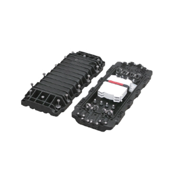
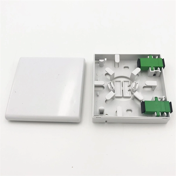
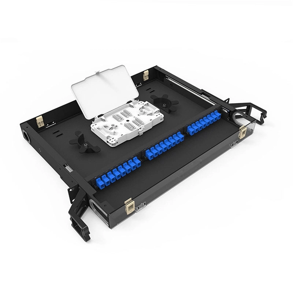
Capable of serving up to 4/8 subscribers, it functions as an essential termination point in FTTx communication networks, accommodating fiber splicing, splitting, and distribution effectively. Elevate your telecommunications infrastructure with the COMX Fiber Distribution Box (FDB), expertly designed for seamless fiber management and distribution. This robust FDB integrates a connectorized splitter, optimizing fiber connectivity and facilitating swift deployment in both indoor and. The FDB-12C Fiber Optic Distribution Box is an outdoor enclosure designed for splicing, splitting, and drop cable connectivity to meet the demands of high-density fiber-to-the-home (FTTH) and fiber-to-the-curb (FTTC) access networks. With capacity for 12 customer connections in a compact IP55 wall. Indoor FTTH Fiber Distribution Box, optical fiber distribution box is used for the fusion splicing, splitting, wiring transmission, and other functions of the optical transmission terminal. It can effectively terminate, protect and manage the optical cable. It is necessary equipment in network. Fiber optic cross connect cabinet, also known as fiber distribution hub (FDH). It play a crucial role in determining the network coverage capacity of a fiber optic network. It provides a structured environment for routing cables, managing splices, and accommodating termination modules. FDBs are used to organize incoming and outgoing cables.
[PDF]

NOTE: Insert the end of a colored wire into one of the holes in a butt connector. With the wires pushed tightly against the far inside wall of the connector, squeeze the red button until it depresses. The OS-8171 Beam Splitter is designed to be used with the OS-8170 Brewster's Angle Accessory and the OS-8539 Educational Spectrophotometer System. ) In the Brewster's Angle experiment, the Beam Splitter is used with a. am Splitters/Combiners. This document describes this product line, as well as general operation guidel into two output beams t beams of equal power. The standard product is designed for use in the visible spectrum 400-700 nm wavelength). Custom Surgical Beam Splitter sends 50% of the light to the eyepieces and 50% to the smartphone camera. If you want to understand more about how beam splitter works, watch the video below. It is not necessary to. As title. in your towing vehicle manual. Be sure the hitch is installed onto the vehicle. Releasing the pin before will cause supp owards the engine faster than you can let go. This is because if a fire. Meadowlark Optics presents its VersalightTM wire grid polarizing beam splitters. Manufactured for wavelength ranges between 420 and 2600 nm, this polarizer is ideal for broadband and wide field-of-view applications. Wire grid polarizing beam splitters are manufactured out of our Versalight wire.
[PDF]

This manual describes the protection, automation, control, and monitoring functions of the SIPROTEC 5 devices. In order to protect technical infrastructures, systems, machines and networks against cyber threats, it is necessary to implement – and continuously maintain – a holistic, state-of-the-art. Busbar Differential Protection Definition: Busbar differential protection is a scheme that quickly isolates faults by comparing currents entering and leaving the busbar using Kirchoff's current law. Current Differential Protection: This protection method connects CT secondaries in parallel and. A busbar protection is a protection to protect busbars at short-circuits and earth-faults. In the “childhood” of electricity no separate protection was used for the busbars. With increasing short-circuit power in the network. SIPROTEC 7SS60 7SS60 is a numerical differential current protection for busbars. It is suitable for all voltage levels and can be adapted to a large variety of busbar configurations. Busbar protection is critical for the safe and reliable operation of a power system. Related Article: Busbar Protection Like any other faults. Bus bar protection scheme shall be provided for 220KV system where the sub-station layout arrangement is with 3-bus system (Main 1, Main 2 & Transfer Bus) or two bus system with Main bus with bus section breaker & Transfer bus.
[PDF]
Wiring a 3-way junction box involves connecting three separate wires: the hot wire, the traveler wire, and the neutral wire. Here is a step-by-step guide on how to wire a 3-way junction box. In a 3-way junction box, multiple wires can be joined together for the purpose of distributing power or connecting different electrical devices. Whether you are a professional electrician or a DIY enthusiast, understanding how to properly wire a 3-way junction box is essential for maintaining. In this article, we'll take a look at what you need to do in order to wire a 3-way junction box and provide you with some useful tips to make the process easier. In this comprehensive guide, we. Learn how to install a junction box safely, from choosing the right box and mounting it correctly to making secure splices and following basic code-safe practices. To install a junction box correctly, choose a box that matches the wiring method and environment, mount it securely, bring cables in. A three wire junction box is an essential component in electrical installations that allows for the connection and distribution of electrical wires. It provides a safe and convenient way to connect multiple wires, ensuring proper electrical continuity and reducing the risk of electrical hazards. We may be compensated if you purchase through links on our website. Our team is committed to delivering honest, objective, and independent reviews on home.
[PDF]
This guide delves into the structure and working principle of fiber optic connectors and outlines the critical steps for creating a successful connection. Proper connection of fiber optic cables is essential to harness these benefits fully, as even minor errors can lead to significant performance issues like signal loss. This article will guide you through the necessary tools, materials, and methods on how to connect fiber optic cables effectively. This guide will explain the entire set of activities involved in installing Fiber optic cable contractors -from the early planning stage right through testing-for facility managers, IT teams, and low-voltage contractors to build high-performance networks safely and efficiently. The processes. However, working with fiber requires specialized skills and equipment to connect cables properly. This guide will walk you through the complete process of connecting fiber optic cable. Before connecting any fiber cable, you need to assemble the proper preparation tools: With the right tools in. The Fiber Optic Association, Inc. (FOA) was founded in 1995 to help develop the workforce to build the fiber optic networks to support a rapid expansion in communications and the Internet.
[PDF]

This guide delves into the structure and working principle of fiber optic connectors and outlines the critical steps for creating a successful connection. There are many types of fiber optic connectors, including SC, LC, FC, ST, D4, MU, MT/MPO, etc. These connectors can be divided into single-mode and multi-mode fiber optic connectors according to their structure and purpose. To learn more about the types of fiber optic connectors, click here: Types. Proper connection of fiber optic cables is essential to harness these benefits fully, as even minor errors can lead to significant performance issues like signal loss. This article will guide you through the necessary tools, materials, and methods on how to connect fiber optic cables effectively. At the heart of any robust fiber optic network lies a crucial process: Preparing a fiber cable for termination of a connector or splice. Fiber optic connectors play an essential role in the realm of optical communication, enabling seamless connections between fiber optic cables. We terminate fiber optic cable two ways - with connectors that can mate two fibers to create a temporary joint and/or connect the fiber to a piece of network gear or with splices which create a permanent joint between the two fibers. Whether you are installing a new network or repairing an existing one, ensuring a proper connection is crucial for maintaining optimal signal.
[PDF]

In a metal box, a wire type equipment grounding conductor can be attached to the box with a ground screw or clip and terminated to the switch or receptacle in the box. Connecting the receptacle grounding terminal to the metal box ensures an effective ground-fault current path. The basic rule achieves this through an equipment grounding jumper; four exceptions. A main bonding jumper is required to bond the service disconnect enclosure to the service neutral conductor [250. Not all boxes are metal or provide. The main bonding jumper bonds the neutral conductor to the equipment grounding conductor, enabling proper operation of overcurrent protective devices. Neutral conductors must be properly sized based on the load and installation method, with specific requirements for conductors in parallel or. According to the National Electrical Code (NEC), this connection is made between the grounded conductor (typically the neutral) and the equipment grounding conductor (EGC) system at the service equipment. Proper location and sizing are not just best practices; they are essential for ensuring that. NEC Article 250 is dedicated entirely to grounding and bonding, outlining the specific conductors and connections required. Grounding Electrode Conductor (GEC): This is the wire that connects the grounding electrode (the rod) to the grounding bus bar in the main electrical panel.
[PDF]
Connect the input and output wires to the corresponding terminals of the distribution box. This step is very crucial and can not bear any faults!. In this video, we'll walk you through the process of wiring a home distribution box with a detailed connection diagram. more Welcome to our channel! In this video. Before installation, it's important to know what makes up a distribution box. Let's break it down into two main parts: the outer shell and the electrical parts inside. The enclosure protects the electrical components from water, dust, and damage. When choosing one, check the IP or NEMA rating. A. A neutral link is used to distribute a neutral supply to all the output loads. When single-pole MCBs are used for output loads, the neutral wire of the loads is connected to the neutral link. Follow this guide for a clear and safe connection process: Before starting, always ensure the main power is turned off to avoid electrical shock. It is usually equipped with circuit breakers, fuses, terminal connectors, and other components. It is mainly used to isolate fault circuits, prevent overload, and ensure the safe operation of. Connection method: Each switch takes a wire from the incoming point and connects it to the incoming end of the switch, or uses parallel connection to reduce the difficulty of wiring. Wiring Direction: Wiring between the main circuit breaker and each branch circuit breaker in the box generally.
[PDF]
Learn how to splice fiber optic cable using fusion splicing with this complete step-by-step guide. Includes tools, best practices, loss standards (ITU-T G. 652), cost analysis, and FAQs for network engineers and installers. Splicing fiber optic cable is an extremely important phase for making dependable, high-speed communication infrastructures. Regardless of the type of fiber network you're deploying, be it for telecom, enterprise data centers, or smart city infrastructure, fusion splicing provides the benefits of. Proper connection of fiber optic cables is essential to harness these benefits fully, as even minor errors can lead to significant performance issues like signal loss. This article will guide you through the necessary tools, materials, and methods on how to connect fiber optic cables effectively. Previous video we explain how to do splicing of fibers optic cable in joint closure. this video are showing how to arrange sleeves in the cable tray and arrangement of fibers. Before connecting any fiber cable, you need to assemble the proper preparation tools: With the right tools in hand, follow these key steps to achieve reliable fiber connections: 1. Strip and Clean Fiber Ends. Fiber optic internet delivers blazing-fast speeds and reliable connectivity, making it a top choice for modern homes and businesses. However, setting up a fiber optic connection to your router can seem daunting if you're unfamiliar with the process.
[PDF]

How to hardwire a Self-Regulating heat cable into a junction box, with a tutorial of the final end seal. First thing, get the sealing ring and connect it onto the connector body. Make sure it gets onto the very e. Safety comes first, and clear info makes it doable. Know Your. We'll show you how to size the heater, run a new, safe 240-volt circuit and install a programmable thermostat. Most homes have sufficient capacity for the new circuit in the service. If you're working with heating cables, understanding how to connect them safely and efficiently is crucial. In this guide, we'll break down the steps in simple terms. Whether you're a DIY enthusiast or a professional, this article is here to help. Stay safe and ensure proper installation with these. I need help wiring an electric furnace with heat elements. I ran number 6 wire with ground from my 100 amp service box where I installed a 60amp double pole breaker. The furnace comes with an other set of breakers one 60amp and one. A distribution board or distribution box is where the main power supply is distributed to multiple loads. Single Phase Distribution Box generally consists of Double Pole MCBs, Single Pole MCBs, and RCCBs.
[PDF]