Connect the input and output wires to the corresponding terminals of the distribution box. Then press the wire onto the terminal with a wire stripper, or tighten the wire with screws. This step is very crucial and can not bear any faults!. This guide provides step-by-step instructions for connecting a distribution box and highlights key factors to consider during installation. What Is a Distribution Box? A distribution box, also known as an electrical distribution board, is a critical component in electrical systems. Whether you're an electrician or a DIY enthusiast, this guide will help you understand the basics of home electrical distribution. Covers wiring, placement, standards, and expert tips for a compliant setup. It takes the incoming power and safely distributes it to different circuits throughout your building. It serves as a central hub for distributing electricity throughout a building, ensuring that power is delivered safely and efficiently to all the required locations.
[PDF]
Connect the input and output wires to the corresponding terminals of the distribution box. This step is very crucial and can not bear any faults!. In this video, we'll walk you through the process of wiring a home distribution box with a detailed connection diagram. more Welcome to our channel! In this video. Before installation, it's important to know what makes up a distribution box. Let's break it down into two main parts: the outer shell and the electrical parts inside. The enclosure protects the electrical components from water, dust, and damage. When choosing one, check the IP or NEMA rating. A. A neutral link is used to distribute a neutral supply to all the output loads. When single-pole MCBs are used for output loads, the neutral wire of the loads is connected to the neutral link. Follow this guide for a clear and safe connection process: Before starting, always ensure the main power is turned off to avoid electrical shock. It is usually equipped with circuit breakers, fuses, terminal connectors, and other components. It is mainly used to isolate fault circuits, prevent overload, and ensure the safe operation of. Connection method: Each switch takes a wire from the incoming point and connects it to the incoming end of the switch, or uses parallel connection to reduce the difficulty of wiring. Wiring Direction: Wiring between the main circuit breaker and each branch circuit breaker in the box generally.
[PDF]

Connect the phase and neutral wires from the input power supply to the input of the Main MCB. If you use a DP MCB for output load then connect both phase and neutral from the output of the RCCB to the input of the Load. This guide provides step-by-step instructions for connecting a distribution box and highlights key factors to consider during installation. What Is a Distribution Box? A distribution box, also known as an electrical distribution board, is a critical component in electrical systems. It serves as a central hub for distributing electricity throughout a building, ensuring that power is delivered safely and efficiently to all the required locations. It is usually equipped with circuit breakers, fuses, terminal connectors, and other components. It is mainly used to isolate fault circuits, prevent overload, and ensure the safe operation of. How to wire a household distribution box? How to pg clamps. When it comes to decoration, many friends like to do it themselves. However, when encountering water and electricity and other links that have a greater impact on the overall decoration, you must do your homework and not implement it. In this video, we'll walk you through the process of wiring a home distribution box with a detailed connection diagram. Whether you're an electrician or a DIY enthusiast, this guide will help you understand the basics of home electrical distribution.
[PDF]

In this video, we'll walk you through the process of wiring a home distribution box with a detailed connection diagram. Whether you're an electrician or a DIY enthusiast, this guide will help you understand the basics of home electrical distribution. more Welcome to our channel! In this video. Single Phase wiring installation is the most common wiring in residential buildings. In Single Phase supply (230V in UK, EU and 120V & 240V in the US & Canada), there are two (one is Line (aka Phase, Hot or Live) and the other one is Neutral) incoming cables from the utility poles to the kWh energy. A distribution board or distribution box is where the main power supply is distributed to multiple loads. And all the switching and protective devices are installed in the distribution box. Single Phase Distribution Box generally consists of Double Pole MCBs, Single Pole MCBs, and RCCBs. An electrical panel box, also known as a breaker box or a distribution board, is a crucial component of any electrical system. It serves as a central hub for distributing electricity throughout a building, ensuring that power is delivered safely and efficiently to all the required locations. What is Distribution Board? Distribution board.
[PDF]
In this video, we'll walk you through the process of wiring a home distribution box with a detailed connection diagram. This guide provides step-by-step instructions for connecting a distribution box and highlights key factors to consider during installation. What Is a Distribution Box? A distribution box, also known as an electrical distribution board, is a critical component in electrical systems. Whether you're an electrician or a DIY enthusiast, this guide will help you understand the basics of home electrical distribution. more Welcome to our channel! In this video. Correct wiring methods for circuit breakers within distribution boxes are fundamental to ensuring electrical safety and compliance with established codes. The distinction between 1P and 2P circuit breakers plays a pivotal role in determining the appropriate protection level for various circuits. Single phase DB box wiring involves connecting the live, neutral, and earth wires to their respective terminals in the distribution board. Wiring a single-phase distribution board (DB) box is a fundamental task for. A residential breaker box, or load center, is the heart of a home's electrical distribution system. This panel routes power from the utility service to every circuit while housing circuit breakers that provide overcurrent protection. Installing or replacing a load center is a complex task involving.
[PDF]

Welcome to our channel! In this video, we'll walk you through the process of wiring a home distribution box with a detailed connection diagram. Whether you're an electrician or a DIY enthusiast, this guide will help you understand the basics of home electrical. This guide provides step-by-step instructions for connecting a distribution box and highlights key factors to consider during installation. What Is a Distribution Box? A distribution box, also known as an electrical distribution board, is a critical component in electrical systems. more Welcome to our. Start by positioning the control panel within 30 feet of both the generator and the main service box. This ensures minimal voltage drop and straightforward conduit routing. Connect the neutral and ground conductors to their. A manual transfer switch is installed next to the main service panel to override the normal electrical service with power from a backup generator during a power outage. Very few homeowners can afford or consider it necessary to supply power to all of the homes electrical devices, fixtures and appliances in the event of a power.
[PDF]
The cost to install fiber optic cable ranges from $1. 50 to $42 per foot, with installation costs accounting for 60-80% of total project expenses. According to the Fiber Broadband Association's 2025 report, median costs are $8 per foot for aerial builds and $18 per foot for. Homeowners and businesses typically pay for fiber optic cable installation based on distance, conduit needs, and labor. The main cost drivers include material type, run length, trenching or aerial work, and any required permits or inspections. This article outlines cost expectations. The initial cost of installing fiber optic cables can vary depending on the chosen installation method and specific project requirements. fiber projects, we've assembled current material rates, labor burdens, and hidden fees. Whether you need singlemode, armored, or indoor plenum, this guide gives you the exact cost per foot of fiber optic cable —. Fiber optic cable installation costs between $1,500 and $7,000 for your home, with prices varying by cable length and installation method. The installation type you choose and the layout of your property determine the total labor and materials needed for your project.
[PDF]
Learn how to splice fiber optic cable using fusion splicing with this complete step-by-step guide. Includes tools, best practices, loss standards (ITU-T G. 652), cost analysis, and FAQs for network engineers and installers. Splicing fiber optic cable is an extremely important phase for making dependable, high-speed communication infrastructures. Regardless of the type of fiber network you're deploying, be it for telecom, enterprise data centers, or smart city infrastructure, fusion splicing provides the benefits of. Proper connection of fiber optic cables is essential to harness these benefits fully, as even minor errors can lead to significant performance issues like signal loss. This article will guide you through the necessary tools, materials, and methods on how to connect fiber optic cables effectively. Previous video we explain how to do splicing of fibers optic cable in joint closure. this video are showing how to arrange sleeves in the cable tray and arrangement of fibers. Before connecting any fiber cable, you need to assemble the proper preparation tools: With the right tools in hand, follow these key steps to achieve reliable fiber connections: 1. Strip and Clean Fiber Ends. Fiber optic internet delivers blazing-fast speeds and reliable connectivity, making it a top choice for modern homes and businesses. However, setting up a fiber optic connection to your router can seem daunting if you're unfamiliar with the process.
[PDF]

Use the SWD or JTAG interface to connect the ST-Link v2 to the STM32 microcontroller. Download and install STM32CubeIDE or another compatible IDE. Install the ST-Link USB driver (available on the STMicroelectronics. The ST-LINK/V2 is an in-circuit debugger/programmer for the STM8 and STM32 microcontrollers. The single wire interface module (SWIM) and the JTAG/serial wire debugging (SWD) interfaces facilitate communication with any STM8 or STM32 microcontroller operating on an application board. ATOLLIC, IAR and KEIL Integrated Development Environments for. How do you use SWD (Serial Wire Debug) for debugging STM32? - HackMD Using SWD (Serial Wire Debug) for debugging STM32 microcontrollers is a powerful way to monitor and control code execution, inspect registers, and analyze faults. Here's a step-by-step guide to set up and use SWD effectively: 1. In addition. This small guide will explain how to connect your debugger to your development board. There are two commonly used connectors which expose only the SWD (Serial Wire Debug) interface or the full JTAG interface. If you are using one of ST's official Nucleo or Discovery boards, you do not have to. To upload a program to a chip from Thomson Semiconductor you need an ST-Link programmer device to connect your PC. Thompson sells branded programmers, adaptors and cables. We'll use an inexpensive ST-LinkV2. They look like AVR programmers but you need to read the pinouts on the side.
[PDF]
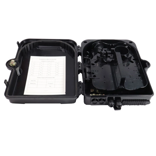
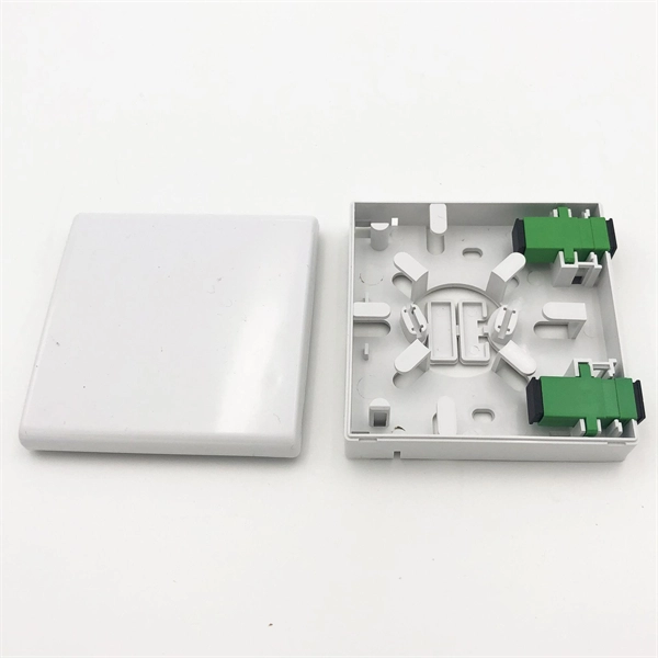
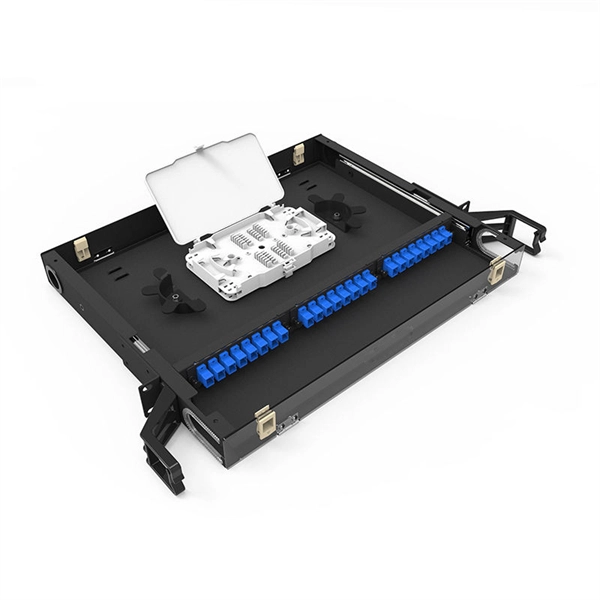
The number of ports in a fiber optic termination box varies from 8 to 96 ports, so you can choose the right junction box for your cable needs. The optical fiber terminal box is the terminal connector of the optical cable, one end is the optical cable, and the other end is the optical cable tail. A Multiport Service Terminal is a hardened, environmentally sealed enclosure that provides multiple pre-connectorized output ports (typically 4, 8, 12, or 16) for drop cables, while accepting a single incoming feeder or distribution cable. Key characteristics: MST boxes are the cornerstone of. The terminal box is a fiber management product used to distribute and protect optical fiber links in FTTH networks. This ethernet port is used to connect the modem to an internet router. Modem router combo devices will generally have four ethernet. A router is more than just a box with blinking lights—it contains multiple ports, each tailored for specific roles, such as LAN, WAN, USB, DSL, and console ports. Understanding the purpose, specifications, and configuration of these ports is essential for achieving maximum network performance. It is also sometimes referred to as an "ONT box" or "fiber box. " What Does an ONT Do? Key Functions Explained Here's a quick breakdown of what an ONT does: The ONT receives light signals from the fiber network and converts them into electrical signals.
[PDF]
Learn how to properly install a pigtail connector in just a few easy steps. No description has been added to this video. Enjoy the videos and music you love, upload original content, and share it all with friends, family, and the world on YouTube. Pigtail connections are most frequently used to ground a switch or electrical outlet and for electrical devices that need to connect to multiple circuit wires. They also come in handy to lengthen circuit wires that are too short to reach a device. A pigtail is composed of three strands of wire. A pigtail connector is a short length of insulated electrical wire that is pre-attached to a device, terminal, or fixture, serving as a flexible bridge between the fixed wiring system and the component. Whether you are a DIY enthusiast or someone facing an electrical issue, understanding how to replace a pigtail connector can be invaluable. This article will walk you through the necessary steps and provide. This is where quality automotive connector replacement steps in. Often, rather than pay thousands of dollars for an entire harness, you can simply replace the damaged connector by a careful de-pin/re-pin or an accurate wire repair. Want more automotive electrical wire repair videos? Click Here Hear. The National Electrical Code (NEC) requires a pigtail to be at least six inches long. Although this standard applies to house wiring, we can use the same for vehicle wiring.
[PDF]
This beginner-friendly guide will walk you through the step-by-step process of fiber optic cable installation for each method, highlighting best practices, tools, and considerations. Proper connection of fiber optic cables is essential to harness these benefits fully, as even minor errors can lead to significant performance issues like signal loss. This article will guide you through the necessary tools, materials, and methods on how to connect fiber optic cables effectively. Starting with site surveys and permissions, to installing fiber optic cable and emphasizing the process as a key stage in mastering fiber optic installation, to the careful handling of cables and high-stakes splicing, each stage is critical. Discover the exact steps, adhere to stringent safety. Single family homes, apartments, condominiums and other multi-dwelling units are increasingly wired with fiber optic cable to future-proof installations and create more reliable, higher-bandwidth and faster speed network and video infrastructures. The processes. Running fiber internally involves extending this high-speed link from the service entry point to a centralized location, such as a dedicated media closet or network rack. This DIY effort is undertaken to maximize performance, improve aesthetics, or relocate the Optical Network Terminal (ONT) to a.
[PDF]

In a metal box, a wire type equipment grounding conductor can be attached to the box with a ground screw or clip and terminated to the switch or receptacle in the box. Connecting the receptacle grounding terminal to the metal box ensures an effective ground-fault current path. The basic rule achieves this through an equipment grounding jumper; four exceptions. A main bonding jumper is required to bond the service disconnect enclosure to the service neutral conductor [250. Not all boxes are metal or provide. The main bonding jumper bonds the neutral conductor to the equipment grounding conductor, enabling proper operation of overcurrent protective devices. Neutral conductors must be properly sized based on the load and installation method, with specific requirements for conductors in parallel or. According to the National Electrical Code (NEC), this connection is made between the grounded conductor (typically the neutral) and the equipment grounding conductor (EGC) system at the service equipment. Proper location and sizing are not just best practices; they are essential for ensuring that. NEC Article 250 is dedicated entirely to grounding and bonding, outlining the specific conductors and connections required. Grounding Electrode Conductor (GEC): This is the wire that connects the grounding electrode (the rod) to the grounding bus bar in the main electrical panel.
[PDF]

The video recommends using a pre-terminated fiber optic assembly and a pair of media converters for situations where your network connection needs to extend beyond 250 feet. You may look to extend your network for either a commercial or residential setting. Yes, fibre optic cables can be extended by using splice closures or optical connectors to join multiple cables together. This allows for longer distances to be covered without loss of signal quality. Yes, it is possible to extend fiber optic cable using various methods and techniques. Fiber optic. Proper connection of fiber optic cables is essential to harness these benefits fully, as even minor errors can lead to significant performance issues like signal loss. This article will guide you through the necessary tools, materials, and methods on how to connect fiber optic cables effectively. This blog post explains how to extend your network over long distances, exceeding the limitations of copper cabling, using fiber optics. This blog post looks at the various options available to installers for responding to these issues; from splicing and field-fit connectors to factory-terminated or pre-connectorization. For network managers and technicians, a poor splice can lead to significant signal degradation, network downtime, and costly troubleshooting. The goal is to align the ends of.
[PDF]

In this step-by-step guide, we will walk you through the process, ensuring that you can seamlessly connect your optical cable and enjoy a clear and uninterrupted audiovisual experience. Optical cables are becoming increasingly popular for transmitting high-quality. Optical audio cables can easily improve your TV's sound by connecting to external speakers. Learning how to connect an optical cable is easy, but there are a couple of gotchas that you should know. Here are the basics: Identify the optical output; if there's a protective plastic cap, remove it. The most common types are: The Toslink optical cable is a standard for transmitting digital audio signals. It uses a plastic or glass fiber to carry light signals from one. You can connect an older flat screen TV to ANY Stereo system, Surround Sound system, or Soundbar. This video shows you step by step how to make audio connections using an digital optical cable. You can use an optical connection even if your audio system does not have an optical socket, and by using. One of the easiest ways to achieve high-quality sound is to connect your TV to a home theater system or soundbar. Easily connect your optical audio cable to your TV! Follow our step-by-step guide for a hassle-free setup and enjoy crystal-clear sound. No wonder how to improve TV sound, right? When the sound is weak, for example, when using an analog sound source, then an optical audio cable possibly will be the.
[PDF]