
In this tutorial, I will show you how you can connect the Optocoupler to Arduino, read the data as Analog or Digital, and if necessary convert the analog values to digital, and how to reduce noise from the sensor. The Infrared Slotted Optical Optocoupler Module is a device that uses infrared light to transmit signals between two electrically isolated circuits. It consists of an infrared emitter (LED) and a photodetector (phototransistor) housed in a slotted enclosure. When an object passes through the slot. Slotted Optocouplers (Photo Interrupters) are very useful sensors, often included in Arduino projects to detect position of moving objects, measure speed of rotation, or linear motion, frequency of events, and many others. They are easy to use, but it is important to understand how they work, so. This tutorial is a comprehensive, practical guide to the Speed Sensor / Tacho Sensor (Slot-Type Optocoupler) (Leobot Product #245). Moreover, a simple application is programmed that shows how to wire and how to program an Arduino when working with the module. In this tutorial, the module is used as an “digital input board”. If you want to use the. In this project, I will talk about Phototransistor Optical Interrupter Switches (Opto Coupler) Module, how this module works and helps in determining the speed of a rotating object and finally I will show you how to Interface Optical Interrupter Switch Sensor with Arduino and measure the speed of a.
[PDF]
Den här guiden går igenom allt du behöver känna till när du vill koppla din egen router till fiber, vilka alternativ som finns, vilka inställningar som krävs och hur du felsöker om något inte fungerar som det ska. However, setting up a fiber optic connection to your router can seem daunting if you're unfamiliar with the process. In this guide, we'll walk you through how to connect a fiber optic cable to a router safely and efficiently. Why Use Fiber Optic Internet? Before diving into the setup, let's quickly. Setting up a fiber internet connection requires understanding key hardware components and following a specific connection sequence to establish your home network. This comprehensive guide combines industry standards with field-tested practices to ensure you achieve a rock-solid.
[PDF]

In the 2020 NEC ®, no more than 18 inches of cable length is allowed between the cable entry to the box and the closest cable support (see image). Below is a preview of the NEC®. ORG for the complete code section. The previous code language could technically allow an unlimited length of coiled up NM cable inside the wall as long as it was secured within 12 inches of the box. This code is based upon the type of box, wires, wire sizes, wire clamps and conduit fittings. Adjustments are made for the ground wire as you will see in the. Calculate and select the right number and spacing of cables for junction boxes using NEC guidelines to ensure safe, code-compliant electrical installations. This step keeps your project safe and. According to the National Electrical Code (NEC), the conductor must be long enough to extend outside the box's opening. This length allows enough room to connect, splice, or terminate wires without strain or damage. If wires are too short, they may fail inspection or create hazards during. The length of wire left inside an electrical box is a matter of strict compliance, safety, and functionality. Having the correct amount of slack ensures that future maintenance, repairs, or device replacements can be performed without difficulty. Proper electrical box fill calculations are critical for code compliance and safety in both residential and commercial installations.
[PDF]

Run the display transceiver [ interface interface-type interface-number | slot slot-id ] [ verbose ] command to view information about the optical module on a specified interface. In optical communication equipment, an optical module (Optical Module) contains several types of semiconductor chips that work together to complete the transmission and processing of optical signals. These chips typically include laser chips, photodetector chips, driver chips, transimpedance. When the optical module on an interface is faulty, you can run the display commands to view information about the optical module. Today, we will deeply analyze the four mainstream models of 100G QSFP28 dual-fiber optical modules: QSFP28-100G-SR4, QSFP28-100G-LR4, QSFP28-100G-ER4 and. The following uses the Moduletek SFP-10G-LR module connected to a Huawei S6700 switch as an example to introduce how to read information of the connected optical module on a Huawei switch. Figure 1 Schematic Diagram of Optical Module Connected to Switch 1. Optical Module Status Check Run the. Upgrade to 100G or 400G optics and save. Cisco Transceiver Modules - Learn product details such as features and benefits, as well as hardware and software specifications. Network administrators have a major challenge determining the right Cisco SFP modules, understanding complex model numbers that directly affect network performance and stability.
[PDF]

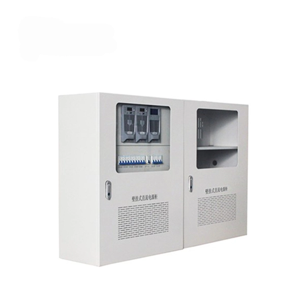
In this video, we'll show you how to connect an energy meter to a distribution board (DB) safely and efficiently. energy meter connection with distribution box How to Connect an Energy Meter to Your Distribution Box Easily Steps to Properly Connect Your Energy Meter to a Distribution Box. It plays a vital role in ensuring the safe and efficient distribution of electricity throughout the premises. What is the wire from the meter to the breaker box? Also. Always begin with disconnecting the main supply before accessing any enclosure containing distribution components. This prevents arc faults and ensures safety when modifying or inspecting current paths. This “meter to panel” wiring establishes the pathway for all incoming electrical power from the grid to the home. Its primary function is to safely and reliably. Distribution Board aslo know as “Panel Board”, “Switch & Fuse Board” or “Consumer Unit” is a box installed in the building containing on protective devices, such as circuit breaker, fuses, isolator, switches, RCDs and MCBs etc. The electric main supply (230V AC & 120V AC in US) is connected through. Changed Texas's reference diagram for the 3 wire network 120/208 Volt single phase self-contained Revised Figures 13, 14, 14b. Limited the meter location from pad mount transformer for PSO. Removed unistrut being listed as an alternative means for mounting the meter box. APCo and TX do not allow.
[PDF]
LC Connectors: Press the latch mechanism and gently pull the connector out. This guide outlines proper methods to safely remove fiber optic cable from modems in your home or office. As an experienced technology writer who has covered broadband advancements for over a decade, I aim to provide readers with trustworthy instructions endorsed by industry experts. Having. Unplugging a fiber optic cable from a modem is a task that requires careful handling to avoid damaging the delicate fibers within the cable. Fiber optic cables are different from traditional copper cables, as they use light to transmit data, and the connectors are more sensitive. This is a popular video tutorial that is often requested by viewers. Fiber optic cables are delicate and require specific handling procedures to maintain their performance and longevity. Is this something that requires a Verizon support tech or can I do it? If so is it as simple as disconnecting and reconnecting or would I have to call support to "reinitiate" my setup. Not my pic, but didn't feel like moving the. Unicom's Wireless Router is a multi-function device providing the following services: • Shared Broadband Internet Access for all LAN users. Page 5 All manuals and user guides at all-guides. com • Virtual Servers. This feature allows Internet users to access Internet servers on your LAN.
[PDF]

The typical setup time for a standard rapid deployment telecom tower ranges from 15 to 60 minutes once the unit arrives on site. However, complex installations requiring guy wires, heavy payloads, or difficult terrain can extend this window to 2-4 hours. How Should You Prepare for Installing Fiber Optic Internet? Before installing fiber optic internet, ensure your business location is ready. Site Planning and Design: This phase involves assessing the need for a new mobile site, selecting a suitable location, and designing the layout of the infrastructure. Conduct radio frequency (RF) planning and coverage analysis to determine areas with poor or no signal. Analyze user demand and. Equipment installation: Once the site is prepared, the equipment can be installed. This includes installing the telecom equipment in the cabinets, setting up the antennas, and running the cables. Testing and commissioning: Once the equipment is installed, it needs to be tested and commissioned to. Assuming the design is completed, we're looking at the process of physically installing and completing the network, turning the design into an operating system. Since. How long does it take to install fiber optic internet? The time it takes to install fiber optic internet depends on your home's layout and existing infrastructure. Will the technician dig up my yard to install fiber optic internet? Your fiber technician will need to either bury the fiber in your.
[PDF]

The compact 1 port ftth fiber termination box can hold 2 cores splicing, termination and coil up to 30 meters long for cable management in FTTH network. The 1 port fiber termination box is available for fiber optic cable coiling, it is great to connect optical cable and pigtail and protect fiber splices from damage. It is small, lightweight, and offers the function of fiber splicing, storage, and termination, mainly used in residential buildings. The maximum distance for single mode fiber optic cable can extend up to several hundred kilometers, making it ideal for long distance data transmission. One type of single mode fiber is known as “G. 652,” which is commonly used in telecommunications networks. Here are some general guidelines: 1. The shorter distance accounts for the. A fiber optic distribution box (FDB) is a protective enclosure for managing fiber optic cables. It organizes connections, splices fibers, and distributes signals in networks like FTTH (Fiber-to-the-Home) or FTTB (Fiber-to-the-Building). It acts as a central point for terminating, splicing, and distributing these cables, providing necessary protection and. The Fiber Optic Association, Inc. (FOA) was founded in 1995 to help develop the workforce to build the fiber optic networks to support a rapid expansion in communications and the Internet. The charter of the FOA was to promote professionalism in fiber optics through education, certification, and.
[PDF]

Step-by-step guide on connecting an inverter to your distribution board for uninterrupted power supply. The process begins with turning off the main power supply to ensure safety. Next, choose an inverter with a suitable capacity to handle your power needs, ensuring it matches the. In this article, you will find information about connecting inverter to distribution box: essential safety tips, step-by-step guidance, and common mistakes that often lead to inverter failure, so that you can avoid them. Last Updated on September 17, 2025 by June The most extensive use of inverter. Connecting an inverter to a distribution board allows you to harness stored energy from batteries or solar panels for powering electrical devices in your home. This setup provides backup power during outages and can also contribute to energy savings by utilizing renewable energy sources. This guide. In this video, we'll guide you through the process of wiring a UPS (Uninterruptible Power Supply) or inverter for your home or office. By following a few simple steps, you can easily learn how to connect an inverter DB wiring diagram. Connecting an inverter DB wiring. Scroll to the bottom of any page to find a sun or moon icon to turn dark mode on or off! I'm not an electrician and do not want to screw this up. What type of wiring do I need to connect the inverter to the distribution box? I have a 1*60A 4*20A FL+LS distribution box with a Sungold Power 5000W 48V.
[PDF]

As fiber optic cables are generally only produced in lengths up to around 5 km, so when lengthier connections are needed, splicing two cables together becomes necessary. So in essence, fiber optic splicing is a process used to join two separate fiber optic cables together. There are numerous use cases for fiber optic splicing. As. The time it takes to splice a fiber optic cable can vary depending on several factors, including the type of splice, the equipment used, and the level of expertise of the technician performing the splice. Proper termination is essential for ensuring optimal performance, reducing signal loss, and maintaining the durability of the connection. Another method of connecting optical fibers is termination or connectorization, which consists of processing the end of a fiber optic bundle so that it can be connected to other fibers or devices through fiber optic. Fiber optic joints or terminations are made two ways: 1) splices which create a permanent joint between the two fibers or 2) connectors that mate two fibers to create a temporary joint and/or connect the fiber to a piece of network gear. Either joining method must have three primary characteristics.
[PDF]

Average Optical Power: How bright the light is (measured in dBm). Too dim? Your signal gets lost in the fiber. Extinction Ratio: The difference between “on” (1) and “off” (0) light power. A higher ratio = cleaner signals. Transmitter Side: An electrical signal hits a laser diode (LD) or LED, which spits out light. Receiver Side: Light enters a photodetector (like a tiny solar cell), which turns it back into electricity. A built-in amplifier boosts the signal for your. The average transmitted optical power refers to the optical power output by the light source at the transmitting end of the optical module under normal working conditions, which can be understood as the intensity of light. In communication, we usually use dBm to represent optical power. However, in practical use, we adopt the average Tx power. The transmission power is related to the. This article provides an in-depth analysis of two key performance indicators of optical modules: transmitter power and receiver sensitivity. Transmitter power characterizes the average optical power output from the laser under rated conditions, while receiver sensitivity indicates the minimum. An optical module is a connecting module that serves as an optical-electrical conversion device. At the receiver end, the optical signals are reconverted into electrical.
[PDF]

In this blog, we will explore the step-by-step process of using a beamsplitter cube effectively, along with some common applications that benefit from this powerful optical tool. Step-by-Step Guide on Using a Beamsplitter Cube. A beam splitter is an optical device that divides an incoming light beam into two separate beams. One beam is typically reflected while the other is transmitted. The ratio of reflected to transmitted light can vary based on the design of the beam splitter. Beam splitters typically come in the form of a reflective device that can split beams into exactly 50/50, half of the beam being transmitted through the splitter and half being reflected. It is a crucial part of many optical experimental and measurement systems, such as interferometers, also finding widespread application in fibre optic telecommunications. Sometimes it is referred to as a half-silvered mirror. Either way, it is a simple material that YOU could use right at home for cool DIY projects like. The beam splitter has played numerous roles in many aspects of optics. For example, in quantum information the beam splitter plays essential roles in teleportation, bell measure-ments, entanglement and in fundamental studies of the photon. Additionally, beamsplitters can be used in reverse to combine two different beams into a single one. Beamsplitters are often classified according to their construction: cube or plate.
[PDF]

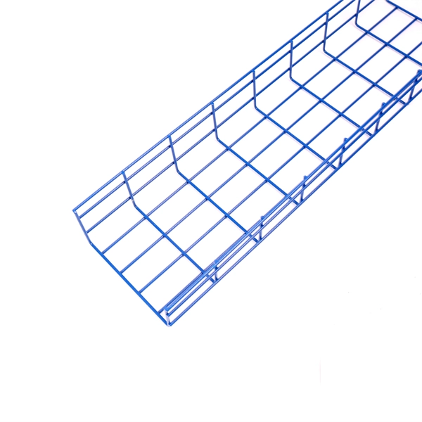
Professional Cable Tray Elbow Making | Metal Fabrication Tutorial Learn how to make cable tray elbows professionally with step-by-step guidance. This video shows metal fabrication techniques, DIY cable tray projects, and tips for perfect bends and joints. Whether you are a DIY enthusiast. The method for producing bridge bend elbows is as follows: Take a 90-degree cable tray bend elbow as an example, and apply the same principles for 45-degree bends accordingly. The length of the bottom side (bottom diagonal) after bending the cable tray should be equal to the width of the cable. This manual is designed to guide workers through the detailed production process of ladder cable trays, including the manufacture of horizontal elbows, tees, crosses, reducing bends, and vertical bends, with emphasis on precision, safety, and quality control. What's Involved in Producing Ladder. The bends, tees, crosses, risers and reducers of wire mesh cable tray can be easily and quickly made live at the project by using a bolt cutter. Since the jaws of the bolt cutter drags a layer of zinc across the cut end and forms a protective layer. When a wire cable tray is cut, the fact that a. How to bend 22. 5 DEGREE OF CABLE TRAY 3 LA. How to bend 90 degree of cable tray 3 line with the same distance :// • HOW TO BEND 90 DEGREE OF CABLE TRAY 3 LINE. Enjoy the videos and music you love, upload original content, and share it all with friends, family, and the world on YouTube.
[PDF]
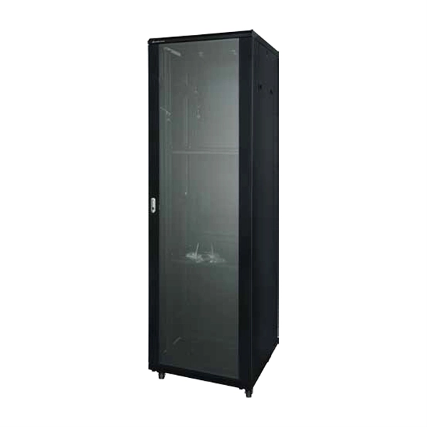
Rack height is measured in rack units (U), where 1U equals 1. Common rack formats include: 24U and below — typical for branch offices or small server rooms. Below is a comprehensive, fully detailed guide covering all standard server rack sizes, form factors, height considerations, depth classifications, and best-practice configuration approaches for professional environments. What Is a Server Rack? Understanding the Core Structure A server rack is a. This comprehensive blog post demystifies the "U" unit in network server accessories—the standard measurement that defines the height of equipment in server racks. A 2U server occupies two rack units, while a 4U server takes up four. Each rack is equipped with mounting rails. A “Rack Unit” (U) is a standard height measure for mounting equipment in a server rack. This article explains definition, planning, installation tips, and trends. At Secure Gates Inc., we provide high-quality 6U, 9U, and 12U Network Rack Cabinets designed to meet the unique needs of professionals, businesses, and data centers. In this blog post, we'll explore what network rack cabinets are, their key benefits, and help you decide which size— 6U, 9U, or 12U. U (rack unit, RU) is a unit of equipment height in a 19" rack. Important: U describes height only, but a server's real "capabilities" are also determined by chassis depth, internal layout, airflow, rails, power, and expansion (PCIe/risers, NVMe.
[PDF]
Options like 6U, 9U, 12U, 15U, and 18U are available in both wall-mounted and free-standing designs, with prices ranging from KSh 7,800 to KSh 30,400 + VAT. All cabinets are equipped with fans, ensuring optimal cooling for your equipment. Our extensive distribution network ensures that our products are readily available wherever you are. Our outdoor networking cabinets prices in Kenya start from KSh 5,000 + VAT for 4U wall-mounted cabinets, up to KSh 54,600 + VAT for 45U free-standing cabinets. ✅Genuine, brand new, sealed stock ✅Price-match against authorized dealers. Network cabinet, data cabinet and server rack cabinet are available at significantly competitive prices in Nairobi, Kenya. We have the best 4U, 6U, 9U, 12U, 15U, 18U, 22U, 27U, 32U, 42U cabinet prices e in Kenya. We are among the leading Cabinets shop in Kenya offering same day delivery. Our brands. Shop Data cabinets of different units such as 4U, 9U, 22U of various measurements like 600x600mm, 600x800mm at best prices in Kenya today. Shop Network Cabinet Available at Best Prices Online from Jumia Kenya – Get Best Offers on Network Cabinet Price in Kenya - Order Now! Fast Delivery & Free Returns. Data Cabinets, also known as network cabinets or Server Cabinets, is part of the core network architecture. They offer safe and secure storage for all your Networking Equipment such as Routers, DVRs, Networking Switches, Servers and much more. Some of the typical applications of Server / Data.
[PDF]
