
Optical modules convert electrical signals into light to move data quickly and reliably in AI systems, enabling fast and smooth data processing. Using advanced optical modules boosts AI system speed and bandwidth, helping handle large data loads with low delay and high efficiency. Optical modules. Laboratory utilities: framework for communication with laboratory equipment and post-processing of data (opticomlib. You can install opticomlib using pip: or from source code: NumPy Compatibility: binary_sequence and electrical_signal now fully support NumPy protocols, allowing direct use with. The optical module serves as a crucial component in optical fiber communication systems, operating at the physical layer, which is the lowest layer in the OSI model. Its primary function is to achieve optoelectronic conversion by converting electrical signals into optical signals and vice versa. An. Learn about the components inside a coherent optical engine, what they do, and how they use modulation to send and receive data. Optical communications over metro, long-haul, and submarine networks once used simple direct-detect technology. That's no longer the case.
[PDF]

Optical modules (also known as fiber optic transceivers) are essential components in modern communication networks, enabling high-speed data transmission by converting electrical signals into optical signals and vice versa. Among various optical module form factors, SFP (Small Form-Factor Pluggable). A fiber optic transceiver (also called an optical transceiver) is a compact module that both transmits and receives data signals through optical fibers. It serves a dual purpose — transmitting electrical signals as light pulses and receiving light pulses to convert them back into electrical form. An optical module usually consists of an optical transmitting device (TOSA, including a laser), an optical receiving device (ROSA, including a photodetector), functional circuits,main control circuit board (PCBA), housing and optical (electrical) interface and other components. How do optical. At the heart of fiber optic technology lies a crucial component: the optical transceiver. Let's explore the key aspects of optical transceivers to help you navigate.
[PDF]
Please view our full RLH price list and contact us at info@fiberopticlink. com if you have any questions or special project needs. A Fiber Optic Patch Panel, also known as an Optical Distribution Frame (ODF) or fiber termination enclosure, is a centralized hardware unit designed to manage, protect, and organize fiber optic cable connections. In an era where data speeds and network reliability are non-negotiable, the patch. fiber optic patch panel, odf, optical distribution frame, fiber distribution panel, rack mount fiber patch panel, wall mount odf, fiber termination box, 1u fiber patch panel, 24 port fiber patch panel, 48 port fiber patch panel, outdoor fiber patch panel, fiber optic odf, sliding patch panel The. Q1: What is the difference between an ODF and a patch panel? An ODF is the entire frame or cabinet managing fiber connections, while a patch panel is a modular unit inside the ODF for cross-connecting fibers. Q2: How many fibers can an ODF handle? It depends on the ODF type; rack-mount units can. ODF is used in the terminal access link of FTTH system. It is a device that splices, distributes, and splits optical fibers and provides protection and management of optical fibers. Belden offers several Fiber Patching Systems. Full patching platforms include FX ECX for LAN environments, FX UHD for high-density fiber channels and the DCX System used primarily in data centers where high amounts of fiber connections and density are the key requirements, as in optical.
[PDF]
Spring knot is used to connect cable tray or trunking to channel. Approved and correct fittings are used. Bonding jumper is installed. Tagging/labelling is provided. Installed containments are free of damages. The purpose of this article is to define the sequence and methodology for the installation of electrical cable trays, cable trunking, cable raceways and boxes, junction and pull boxes. These guidelines are not intended to cover all details or variations in cable ladder and cable tray. Hubbell's NEXTFRAME® Ladder Tray is the effective and widely used cable runway that supports and delivers bundles of cable between cabinets, racks, and closets, along walls, and suspended from ceilings. The Ladder Tray features light, rugged, tubular steel construction. It is designed for. bow fittings, etc. ) Of the tray being mounted. Supports should provide strength and working load sufficient to the load require ents of the cable tray system being supported. Structural building members should never be cut, and cable trays should not be installed in hoist ways or where subject to. Welcome to our comprehensive guide on installing wall brackets for different types of cable trays and cable ladders! In this video, we will walk you through the installation process for four different types of wall brackets, specifically designed for cable trays, mesh cable trays, and cable.
[PDF]

In this step-by-step guide, we will walk you through the process, ensuring that you can seamlessly connect your optical cable and enjoy a clear and uninterrupted audiovisual experience. Optical cables are becoming increasingly popular for transmitting high-quality. Optical audio cables can easily improve your TV's sound by connecting to external speakers. Learning how to connect an optical cable is easy, but there are a couple of gotchas that you should know. Here are the basics: Identify the optical output; if there's a protective plastic cap, remove it. The most common types are: The Toslink optical cable is a standard for transmitting digital audio signals. It uses a plastic or glass fiber to carry light signals from one. You can connect an older flat screen TV to ANY Stereo system, Surround Sound system, or Soundbar. This video shows you step by step how to make audio connections using an digital optical cable. You can use an optical connection even if your audio system does not have an optical socket, and by using. One of the easiest ways to achieve high-quality sound is to connect your TV to a home theater system or soundbar. Easily connect your optical audio cable to your TV! Follow our step-by-step guide for a hassle-free setup and enjoy crystal-clear sound. No wonder how to improve TV sound, right? When the sound is weak, for example, when using an analog sound source, then an optical audio cable possibly will be the.
[PDF]
In this guide, I'm excited to share with you 15 creative and surprisingly simple ways to transform your ugly electrical box from an eyesore into a part of your home you might actually want to show off. There are actually a whole host of creative and, more importantly, stylish ways to conceal your breaker box or electrical panel without blocking access or impeding functionality. But before you get started, make sure you double-check with an electrician and your local codes. Some electrical codes. Either way, here are unique electrical panel cover ideas to give you some inspiration. Don't let an ugly gray metal electrical panel ruin your decor! Check out these creative solutions for covering one in any room (removable, of course). Our editors and experts handpick every product we feature. We may earn a commission from your purchases. Which is exactly where I was struggling, we have an electrical panel directly in our dining room (small space problems). These fellow bloggers turned their electric panel doors from eyesores into focal points and pieces of art.
[PDF]

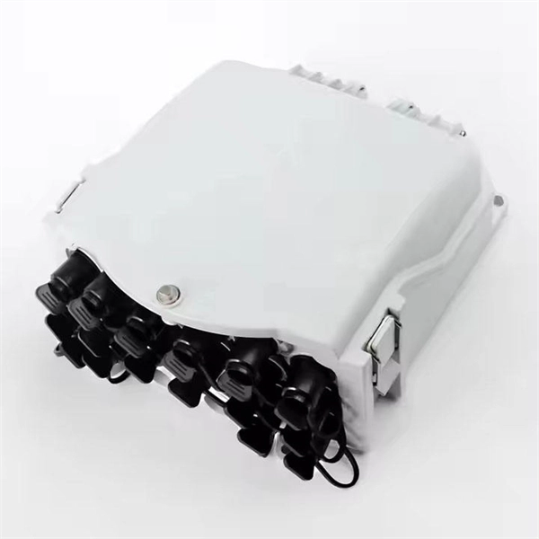
If you are ever in need of checking your ONT, this video will show you how to do so and what it is you are looking for. Always remember to securely close the box afterwards to prevent any damage to the facilities inside. more. A fiber termination box is the standard instrument used in fiber optic networks to connect, secure, and protect optical fibers at the terminating point. It functions as a junction between the incoming fiber cable and the outgoing customer-side fiber cable, where one fiber can be spliced, patched. Open the Fiber optic terminal box. Check and prepare installation tools and accessories. Prepare the cable according to the design. An ONT, or Optical Network Terminal, is the box where your fiber internet connection enters your home to power your fiber network. Your ONT is typically located in your garage, basement or outside your home within a few feet of your home's power box. It serves as a termination point for optical fibers, providing a secure and organized space for connecting and managing fiber optic cables. A fiber pigtail is a specific hardware connection used for cable termination. Proper installation and maintenance of FTBs are essential to ensure the reliability and performance of the network infrastructure.
[PDF]

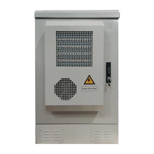
How often you check the enclosure depends on where and how you use it. You must follow rules for dangerous. Explosion proof distribution boxes and electrical enclosures are critical components for ensuring safety in hazardous environments. They are designed to contain internal explosions and prevent ignition of surrounding flammable gases or dust. Since the ATEX Directive came into force, equipment for explosive. We supply certified explosion proof distribution box & Atex Transformer -Appleton, ATKON, CZ, CEAG, brands for safe and reliable industrial use. Flameproof enclosure (Ex d IIB+H2), which can be used as feed distribution equipment in control and distribution system (such as distribution box, switch box of main circuit, control box, terminal box or motor starting box etc. ) ·Enclosure: stainless steel. Equipped with specialized hinge. Ex Industries (exindustries) is a global supplier of advanced hazardous area solutions, offering a wide portfolio of certified products including explosion proof electrical boxes, explosion proof junction boxes, explosion proof lighting, intrinsically safe barrier systems, explosion proof cables. These NEC-rated enclosures are often used to protect your people and parts from explosive risks in plants that handle or make fuel, bulk powders, and chemicals. Plus, they lock out water to keep your electrical components dry. Lift-Off Cover— The removable, screw-secured cover is best for full.
[PDF]
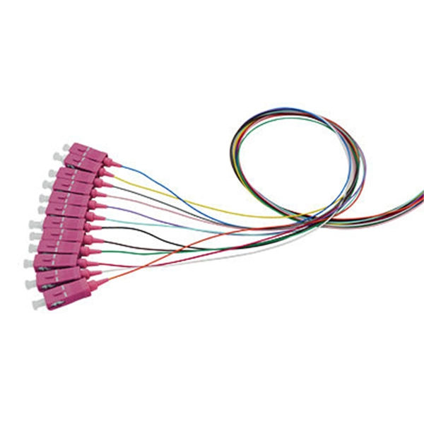
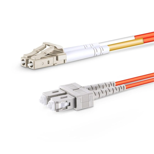
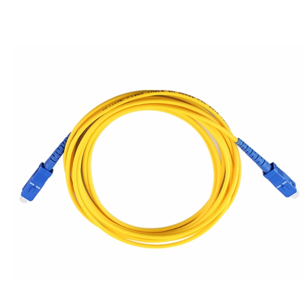
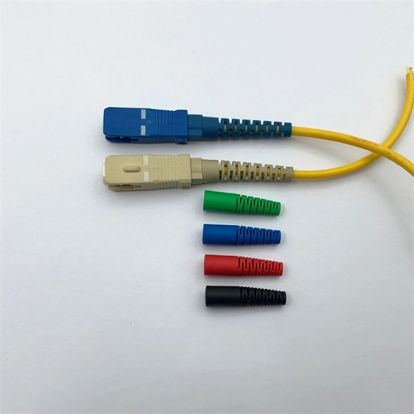
Here's what to consider: 1. Fiber Type Choose single-mode for long-distance transmission and multimode for shorter runs. Connector Compatibility Match the connector (LC, SC, ST, etc. ) with your equipment ports. Fiber Count Select based on network scale—higher. Executive Summary: A fiber optic pigtail is one of the most commonly specified yet least understood components in structured cabling. Get the wrong connector type, the wrong polish, or skip proper fusion splicing technique—and you're looking at elevated signal loss, increased back reflection, and a. Today, I'll show you how to pick the right patch cord or pigtail — step by step. You plug it into a switch, router, or patch panel. A pigtail is for splicing. You fuse it to a. A fiber pigtail is a single, short, usually tight-buffered fiber optic cable with a factory-installed connector on one end, and un-terminated fiber on the other end. Fiber optic pigtails are used to terminated fiber optic cables via fusion splicing or mechanical splicing as shown in the picture. In this guide, we'll break down what fiber optic pigtails are, how they work, their types, and how to choose the right one for your application. By the end, you will have a comprehensive understanding of why pigtails deserve a place in every fiber deployment toolkit. Each type has its own unique design, size, and compatibility features. Understanding these differences is essential for choosing the right pigtail for your network.
[PDF]
In this article, we will guide you through the step-by-step process of opening an electrical box safely and effectively. We will also highlight the necessary tools and materials you will need to complete the task. The electrical service panel, commonly known as the breaker box, acts as the central distribution hub for all electrical power entering a home. This metal enclosure receives high-voltage current from the utility company and safely divides it into various circuits that supply power to lights. So, before we dive into the discussion, here's a list of tools that you must have. Electric Drill/Screwdriver 2. Personal Protective Equipment Step 1. Clear your working area Step 2. Estimate the cover's weight Step 4. It is responsible for controlling and distributing the electrical current throughout your house, ensuring the safety and efficiency of your electrical appliances and devices. This article details the process of installing them, which helps you comprehend distribution boxes. An electrical panel box, also known as a breaker box or a distribution board, is a crucial component of any electrical system. Whether you're a seasoned DIY enthusiast or simply looking to understand the procedure, this guide will provide a clear roadmap to ensure a smooth and safe transition. Let's embark on this.
[PDF]
Dispersion of an optical fiber directly affects the bandwidth and distance capability of the fiber optic link and reduces its efficiency. The higher the dispersion, the lower the potential data rate and transmission distance. Fiber optic cable transmission distance is determined by two primary physical factors that affect signal quality as light travels through the fiber medium. The greater the distance, the greater. With amplifiers, such as Erbium-doped fiber amplifiers (EDFAs), the distance can be extended to 600 miles or more, and even further with additional amplifiers for long-haul applications. In this guide, we'll explore how fiber optic cables function, the maximum distances for different types of fiber optics, and tips for. Fiber optics transmits information by sending light signals through thin strands of glass. While this technology offers higher speeds and longer distances than traditional copper wiring, physical limitations impose distance constraints. Light pulses degrade as they travel over long spans, primarily. The maximum distance a fiber optic cable can transmit data reliably is influenced by several key factors, primarily the inherent properties of light and the physical characteristics of the fiber itself. Understanding these limitations is essential for designing efficient and robust internet.
[PDF]
In this tutorial, we will show you how to fusion splice two fiber optic strands together in an easy 12 step process. The answer lies in splicing, both fusion and mechanical. Whether you're a professional technician or a DIY enthusiast, understanding the process of fusion splicing fiber optic cables is essential for maintaining high-speed communication networks. - Fiber Instrument Sales What is Fusion Splicing? How fiber optic splicers work, types, what they are used for. Steps to use this equipment and including how to test your fiber splice. The guide covers everything from basic principles of fusion splicing to detailed procedures; it is intended to provide both newbies and professionals with the necessary knowledge and skills. The operation and skills of fiber optic fusion splicing technology can be mainly divided into five steps: fiber stripping, fiber cutting, fiber melting, fiber sleeve, and fiber winding. And tools used for fiber fusion: fusion splicer; fiber cleaver; cable stripper; fiber optic stripper; alcohol;.
[PDF]

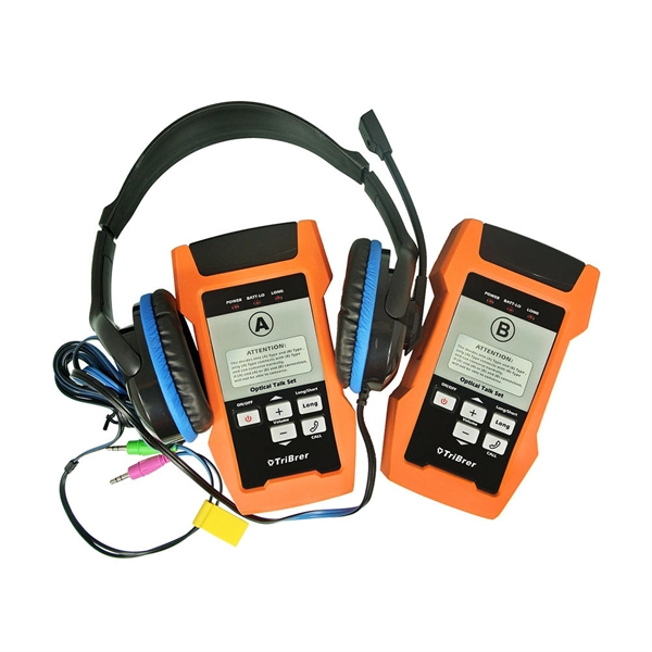
The core measurement procedure follows five steps: Turn on the meter and let it warm up. Most meters need a brief stabilization period before readings are reliable. Check your model's manual, but a minute or two is typical. Set the wavelength to match your light source. Fiber loss is the difference between the power when light is coupled from the transmitting end to the fiber and the power when the light reaches the receiving end. Generally speaking, when measuring the. An optical power meter measures the strength of light traveling through a fiber optic cable, giving you a reading in dBm (decibels relative to one milliwatt). The basic process is straightforward: turn the meter on, set it to the correct wavelength, clean your connectors, plug in, and read the. A power meter and light source are essential test tools that work in tandem to measure fiber optic cable loss and evaluate the quality of optical links. They provide the data necessary to quantify signal loss and pinpoint issues that could impact network performance. Here's how they work: A power. You measure optical power in dBm or insertion loss in dB. Verify light travels from transmitter to receiver. We'll give you the basic information you need and provide some printable references.
[PDF]

This guide discusses common cable tray problems, from loosening and corrosion to grounding issues and installation errors, along with strategies for prevention and resolution. Understanding the root causes of cable tray failures is the first step toward ensuring system reliability. Let's delve into. How far apart should cable trays be supported? What's the risk if support spacing is too wide? Can I reconfigure tray layouts later? What's the best tray material for outdoor use? How can I reduce electromagnetic interference in trays? What are the common faults in cable? What is the most common. The products can be widely used in construction, energy, power, plant. There are five common ways to fix the cover plate of cable tray elbow supplier: pressing plate fixing, screwing fastening, clasping fixing, padlock fixing and seven-shaped buckle fixing. I would like to introduce to you the five. Steel cable trays form the backbone of organized and efficient electrical wiring in industrial, commercial and infrastructure projects. Whether installed as stainless steel cable trays, these components offer durable and flexible solutions for routing cables safely. However, like any other infrastructure, cable trays are prone to failures that can result in serious safety hazards, financial losses, and downtime. The specific operations are as.
[PDF]

In this tutorial by TiFi Design, you'll learn in-depth how to create. In this tutorial by TiFi Design, you'll learn in-depth how to create. In this geometry nodes tutorial, learn how to design procedural fiber optics in Blender! You'll learn in-depth how to create, distribute, and reshape splines; capture attributes; and use those attributes to build a vibrant shader. more In this geometry nodes tutorial, learn how to design. Building Information Modeling (BIM) uses multi-dimensional, spatial models that incorporate detailed product information for the building components. Blender enthusiast and YouTuber, I make video. Just wanted to share my recent geometry nodes tutorial on how to design brilliant fiber optics. I hope you enjoy it! https://youtu. be/l-OGJml_sRQ The largest. When communicating between systems, either via the internet or via an internal network system, a medium needs to be in a place that can facilitate the transmission of data, both sending and receiving. There are numerous options available for laying down communication mediums, such as coaxial cable. The Computer-Aided Design ("CAD") files and all associated content posted to this website are created, uploaded, managed and owned by third-party users. Each CAD and any associated text, image or data is in no way sponsored by or affiliated with any company, organization or real-world item.
[PDF]