This video will show you how to wire a Painless Performance headlight relay into your OBS Chevy / GMC truck or Tahoe to keep the low beams on when you run the high beam lights for much better light coverage in night driving conditions. more. If your headlights suddenly seem too high, too low, or uneven, you likely need to adjust the beam pattern on your headlights. In many cases, poor headlight aim comes from extra weight in the rear of the vehicle. For example, a loaded trunk, hunting gear, tools, or a trailer can push the back end. When we want to replace and upgrade our car headlights, we will pay attention to their brightness and beam pattern. But there is one important factor that is often overlooked - the cutoff line. You can. A blown out low beam bulb can make it difficult to see at night and driving with your high beams on all the time can make it difficult for other drivers to see. Fortunately, fixing a bad low beam is a straight forward process in the majority of vehicles that can be done by most people without just. This DIY will explain how to hookup your DRL's to stay on with your low beams WITHOUT running a switch in the cab. One 30 amp max fuse holder 5. Length of assorted color 14-16 guage wire 6. Female connectors (blue) 7. The right pattern illuminates potential hazards, complies with legal standards, and ultimately keeps you safe. more Audio tracks for some languages were automatically.
[PDF]
In this blog, we will explore the step-by-step process of using a beamsplitter cube effectively, along with some common applications that benefit from this powerful optical tool. Step-by-Step Guide on Using a Beamsplitter Cube. 📦 For purchasing, use the RP Photonics Buyer's Guide for beam splitters. It provides an expert-curated supplier directory, buyer-focused technical background information, and structured selection criteria to support professional procurement decisions. What are Beam Splitters? A beam splitter (or. An Optical Beamsplitter is an optic or optical device that is used to split a beam of light in two. Newport offers a wide variety of Beamsplitters in various shapes. It is a crucial part of many optical experimental and measurement systems, such as interferometers, also finding widespread application in fibre optic telecommunications. One beam is typically reflected while the other is transmitted. The ratio of reflected to transmitted light can vary based on the design of the beam splitter. Our plate beamsplitters have a coated front surface that determines the beam splitting ratio while the back surface is wedged and AR coated in order to minimize ghosting and interference effects.
[PDF]
A beam splitter or beamsplitter is an optical device that splits a beam of light into a transmitted and a reflected beam. It is a crucial part of many optical experimental and measurement systems, such as interferometers, also finding widespread application in fibre optic telecommunications. DesignsIn its most common form, a cube, a beam splitter is made from two triangular glass which are glued together at their base using polyester,, or urethane-based adhesives. (Before these synthetic,. Beam splitters are sometimes used to recombine beams of light, as in a. In this case there are two incoming beams, and potentially two outgoing beams. But the amplitudes. For beam splitters with two incoming beams, using a classical, lossless beam splitter with Ea and Eb each incident at one of the inputs, the two output fields Ec and Ed are linearly related to the inputs thro.
[PDF]
In this article, we will explore the six proven ways to fix optical cable issues, enabling you to get back to enjoying high-quality sound and visuals without a hitch. Before delving into troubleshooting, it's useful to understand exactly what an optical cable is and how it works. Optical cables, often referred to as fiber optic cables, have become integral to our everyday lives, delivering high-speed internet and crystal-clear audio and visual signals. However, like any technology, issues may arise, leading to anxiety and frustration when your optical cable isn't. Whatever the case, In this article, we have discussed the fixes that you can apply when your optical cable is not working. Since a damaged optical cable will prevent you from using your external speakers, you need to solve it as soon as possible. These cables are made entirely of dielectric materials, such as. Optical cables have revolutionized how we transmit audio and visual signals, providing a crisp connection with minimal interference. They use light to carry data, making them an excellent option for connecting devices like televisions, sound systems, Blu-ray players, and gaming consoles. However. While a cut or damaged fiber optic cable can temporarily take your network down, it is possible to quickly fix the cable with the right tools. This wikiHow article will teach you how to splice a cut fiber optic cable back together with a fiber optic stripper and cutter and a fiber optic crimper.
[PDF]
For stubborn residues, xylene, acetone, or 70% ethanol in distilled water can be used, with xylene being the most effective but potentially damaging to optical components. It is crucial to avoid rubbing dry cloths on dry glass surfaces and to wear latex gloves to prevent. I guess there are two ways to look at this ; the oil will cause dirt and such to stick to bar but might help on wear and dry nothing sticks. What's everyone's thought on this and what do you do ? mat60, amateur cutter, Slocum and 9 others like this. The fresh grease forces out. Should I grease the splitter beam or leave it clean? I guess the grease will attract dust and sand, causing grinding paste and potentially more wear and tear. My splitter came with grease nipples on the beam, so I often added some grease. I am just not convinced this is a good idea. Any advice?. This discussion focuses on the proper cleaning techniques for polarizing beamsplitter cubes, emphasizing the importance of using appropriate materials and methods to avoid damaging coatings. The recommended cleaning solution is "Sparkle" brand glass cleaner (purple variant), applied with Q-tips or.
[PDF]
Step1 : Identify the optical cabinet and network operating center, and find the fiber optic splitter. Step 5: Patching from the splitter port to the user. Fiber optic patch cords must be installed correctly to ensure best network performance, reduce signal loss, and protect the sensitive fibers. Whether you're connecting a data center, a corporate network, or a high-density fiber infrastructure, correct installation methods are essential. Yingda. You can put in a fibre patch cord at home. You just need to follow easy steps and be careful. Planning helps you pick the right cord for your network. Be gentle when you handle the cord. Fibre patch cords last longer and are tougher than. This article will guide you through the necessary tools, materials, and methods on how to connect fiber optic cables effectively, ensuring you achieve optimal performance from your fiber optic network. Have a network installation project? Fiber Optic Cables: The primary medium for your connections. NS Comm provides enterprise-grade fiber optic patch cables engineered for maximum reliability and low-loss performance. However, proper installation techniques are essential to unlock their full potential. This guide will help you understand fiber construction, installation steps, real attenuation. Correct patch-cord installation is essential for maintaining low insertion loss, stable return loss, and long-term reliability in both indoor and outdoor fiber networks.
[PDF]

In this blog, we will explore the step-by-step process of using a beamsplitter cube effectively, along with some common applications that benefit from this powerful optical tool. Step-by-Step Guide on Using a Beamsplitter Cube. A beam splitter is an optical device that divides an incoming light beam into two separate beams. One beam is typically reflected while the other is transmitted. The ratio of reflected to transmitted light can vary based on the design of the beam splitter. Beam splitters typically come in the form of a reflective device that can split beams into exactly 50/50, half of the beam being transmitted through the splitter and half being reflected. It is a crucial part of many optical experimental and measurement systems, such as interferometers, also finding widespread application in fibre optic telecommunications. Sometimes it is referred to as a half-silvered mirror. Either way, it is a simple material that YOU could use right at home for cool DIY projects like. The beam splitter has played numerous roles in many aspects of optics. For example, in quantum information the beam splitter plays essential roles in teleportation, bell measure-ments, entanglement and in fundamental studies of the photon. Additionally, beamsplitters can be used in reverse to combine two different beams into a single one. Beamsplitters are often classified according to their construction: cube or plate.
[PDF]

With the large variety of beamsplitters available, the designer needs to take many factors into consideration. This article and its illustrations will go a long way toward making the correct choice less of a risk. All curves show typical performance. A beam splitter (or beamsplitter, power splitter) is an optical device which can split an incident light beam (e. a laser beam) into two (or sometimes more) beams, which may or may not have the same optical power (radiant flux). It is a crucial part of many optical experimental and measurement systems, such as interferometers, also finding widespread application in fibre optic telecommunications. One beam is typically reflected while the other is transmitted. Beamsplitters are often classified according to their construction: cube or plate. In this blog, we will explore the step-by-step process of using a beamsplitter cube effectively, along with some common applications that benefit from this powerful optical tool. Step-by-Step Guide on Using a Beamsplitter Cube Step 1: Understanding the Cube Orientation: A beamsplitter cube is a. A beam splitter is an optical device that splits beams (such as laser beams) into two (or more) beams. Beam splitters typically come in the form of a reflective device that can split beams into exactly 50/50, half of the beam being transmitted through the splitter and half being reflected.
[PDF]

Its red laser shines through most yellow-jacketed optical fibers to help you pinpoint breaks, bends, faulty connectors, splices and other causes of signal loss. It has a reach of up to 5 km. The RPEN-210 is a necessity tool that should not be missing from any fiber plant manager or fiber optic installing technician. The Visual Fault Locator (VFL) Pen has a visible red light source centered on 650nm. Tool sends visible light over a fiber strand with a 10mW power, good enough to reach. The FLS-140 is the easiest way to identify optical fibers from end to end and locate polished connector endfaces. 5 dBm, but it couples approximately 3 dB less into a fiber. This is a Class 1 unit; the Class 1 limit is +3 dBm. The Class 1 limit (+3 dBm/2 mW) is intrinsically safe in all circumstances and is. This VFL has a fiber stub; its total emission is -1. 30 years of experience in R&D and manufacturing - Jilong JILONG launched the VFL-22M mini red light pen, pocket design, small and portable, integrated VFL/LED function, strong and stable light source, strong penetrating. A visible laser radiation source is one of the simplest devices and is designed to produce red light with a wavelength of 650 nm, which is transmitted through an optical fiber. The main purpose of this device is to locally detect various types of damage (such as breaks, bends, poor splicing, etc.
[PDF]
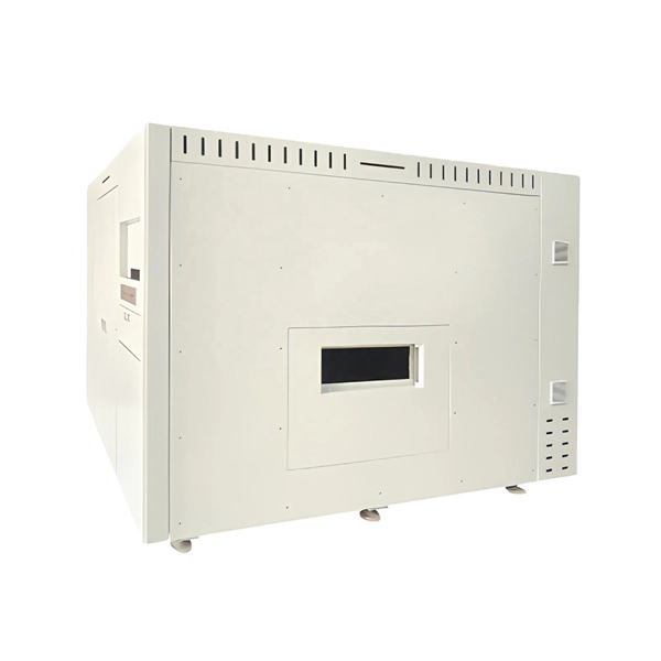
The typical cost of 1U space in a 45U server cabinet is $55. Therefore: Average cable management cost is . Basic cable management systems (cable trays, ties): $200 to $1,000 per rack. Power and Cooling Infrastructure Power Distribution Units (PDUs): $200 to $1,500 per unit, depending on capacity. 73/U The. Durable & Easy to Install: Made from sturdy plastic for long-term use in IT environments. Installs easily on standard rack rails using the included M6 screws-no special tools required Each item has a unique code that we verify before shipping. com Return Policy: Amazon. com. Sysracks offers a wide array of data closet cable management products for different devices: Horizontal managers: Our 1U wire managers are designed to suit any 19” cabinet. This allows structured routing of twisted-pair wires and patch cords and ensures the correct cord radius to prevent twisting. Shop top-quality rack cable managers for efficient data center wiring. Get a horizontal/vertical cable manager to safely organize and protect your cables. Our 1U and 2U cable managers reduce slack, improve airflow, and create clean, serviceable rack layouts designed for scalability.
[PDF]

Excavate the cable at the break point and use a fiber optic cutter to remove the damaged section. Use a high-precision fiber cleaver to prepare the fiber ends for splicing. Step1 : Identify the optical cabinet and network operating center, and find the fiber optic splitter. Step 2: Identify the splitter number. Step 4: Find the optical fiber port and cable sequence that leads to the user. 2) The. Here are the steps to patch a fiber cable. Make sure the connectors are free from dust or dirt and that there is no damage to the cable's. When fiber cables sustain damage, specialized repair techniques help restore connectivity and maintain data integrity. This comprehensive guide outlines professional fiber optic repair protocols that align with industry best practices. Adhering to precise methodologies, we can mend impaired cables. Learn how to splice fiber optic cable step by step in this complete guide! In this video, you'll see the full fiber splicing process — from fiber preparation, cleaving, and fusion splicing to final testing. Whether you're a network technician, IT professional, or telecom operator, you'll find practical steps, tools, and tips to restore. By understanding these key elements and following the outlined steps, you can effectively repair fiber optic cables and maintain the high-performance network necessary for today's demanding communication needs. When it comes to ensuring nice network experiences for users, the condition of a fiber.
[PDF]

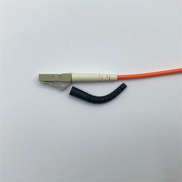
The compact 1 port ftth fiber termination box can hold 2 cores splicing, termination and coil up to 30 meters long for cable management in FTTH network. The 1 port fiber termination box is available for fiber optic cable coiling, it is great to connect optical cable and pigtail and protect fiber splices from damage. It is small, lightweight, and offers the function of fiber splicing, storage, and termination, mainly used in residential buildings. The maximum distance for single mode fiber optic cable can extend up to several hundred kilometers, making it ideal for long distance data transmission. One type of single mode fiber is known as “G. 652,” which is commonly used in telecommunications networks. Here are some general guidelines: 1. The shorter distance accounts for the. A fiber optic distribution box (FDB) is a protective enclosure for managing fiber optic cables. It organizes connections, splices fibers, and distributes signals in networks like FTTH (Fiber-to-the-Home) or FTTB (Fiber-to-the-Building). It acts as a central point for terminating, splicing, and distributing these cables, providing necessary protection and. The Fiber Optic Association, Inc. (FOA) was founded in 1995 to help develop the workforce to build the fiber optic networks to support a rapid expansion in communications and the Internet. The charter of the FOA was to promote professionalism in fiber optics through education, certification, and.
[PDF]

While optical power meters are the primary power measurement instrument, optical loss test sets (OLTSs) and optical time domain reflectometers (OTDRs) also measure power in testing loss. TIA standard test FOTP-95 covers the measurement of optical power. This measurement is the basis for loss measurements as well as the power from a source or presented at a receiver. Typically both transmitters and receivers have receptacles for fiber optic connectors, so measuring the. You need a power meter to measure power in a fiber optic system; most power meters come with a screw-on-adapter that matches the connector being tested and a little aid from the network electronics to turn on the transmitter. During the measurement of power, the meter must be set to the proper. Fluke Networks sets the standard in network testing with its advanced range of fiber optic power meters and fault locators, designed to ensure the highest precision in fiber optic meter readings and power evaluations. This is measured in decibels (dB). Splitters, fusion splices, connectors and. To use a power meter for fiber optic testing, always clean connectors first with lint-free wipes or click-to-clean tools. Select the correct wavelength and set your reference. Consistent procedures ensure accuracy.
[PDF]

The first thing you should do is locate the fiber optic cable that comes from the service provider. Once inserted, make sure it is securely. However, setting up a fiber optic connection to your router can seem daunting if you're unfamiliar with the process. Why Use Fiber Optic Internet? Before diving into the setup, let's quickly. Ensure your fiber optic router has an available WAN (Wide Area Network) or Ethernet port for the fiber optic modem. It's thin, flexible, and usually comes with connectors on both ends. Power Cables: Get power cables for both the. The fiber optic cable does not plug directly into a standard home router because the signal type must be translated. The fiber line terminates at the Optical Network Terminal (ONT), which is typically supplied and installed by the internet service provider. This specialized equipment serves as the. The process to connect fiber optic cable to router requires careful attention to detail, but I'll walk you through every critical step with the precision and clarity you deserve. Here's a step-by-step guide to help you through it. Understand the Basics Before diving in, familiarize yourself with the components involved:. Follow along as we take you through the step-by-step process of installing fiber internet! From preparing the site to connecting the final cables, we'll show you what goes into bringing high-speed internet to your doorstep. Whether you're a tech enthusiast or just curious about how it all w.
[PDF]
We're talking anywhere from $45 for a small residential unit to over $6,000 for industrial-grade modules. In this guide, as a professional hollow fiber membrane manufacturer, I'll break down exactly what influences these prices and how to get the best value for your specific. What's the hollow fiber membrane price going to set you back? Here's the deal: Hollow fiber membrane costs vary WILDLY. The Global Hollow Core Fiber Market will grow at a CAGR of 10. 92% from 2025 to 2031, reaching USD 24. Industrial uses and innovation fuel this surge, with the market predicted at USD 11. The pricing dynamics of the hollow core fiber market are influenced by factors. Check each product page for other buying options. Price and other details may vary based on product size and color. Need help?. The price of hollow fibers varies significantly based on material composition, manufacturing process, sustainability, and performance characteristics. Understanding the different types helps buyers make informed decisions for both commercial and personal applications. Fibers colored during the. Cobetter hollow fiber filters are made of low-binding modified polyethersulfone membranes (m-PES) that deliver excellent filtration performance. The low shear stress makes it ideal for the processes of cell harvest, clarification, diafiltration and concentration where gentle and fast separation is.
[PDF]
