
Follow a step-by-step process: mark the location, drill holes, insert anchors, and secure the box for a weatherproof fit. Apply weatherproof sealant around the box edges and cable entry points to prevent water ingress. Installing an electrical box on an exterior wall can seem daunting, but with the right guidance, it can be a straightforward task. Whether you are adding an outdoor outlet for convenience or setting up lighting, understanding the process is key. This guide will walk you through the essentials of. An electrical junction box is a protective housing designed to enclose and shield electrical wire connections or splices. For outdoor installations, the box must defend these sensitive splices against moisture, dust, temperature fluctuations, and physical impacts. Safety remains crucial during installation. It takes the incoming power and safely distributes it to different circuits throughout your building. Whether in a home or an industrial facility, this box keeps your electrical setup organized, functional, and efficient. Whether adding a GFCI outlet for safety or upgrading an exterior outlet for weather-resistant durability, it's essential to follow proper electrical wiring. In this video, I'll show you how to install a weatherproof outdoor electrical box — safe, secure, and code-compliant.
[PDF]
Step1 : Identify the optical cabinet and network operating center, and find the fiber optic splitter. Step 5: Patching from the splitter port to the user. Fiber optic patch cords must be installed correctly to ensure best network performance, reduce signal loss, and protect the sensitive fibers. Whether you're connecting a data center, a corporate network, or a high-density fiber infrastructure, correct installation methods are essential. Yingda. You can put in a fibre patch cord at home. You just need to follow easy steps and be careful. Planning helps you pick the right cord for your network. Be gentle when you handle the cord. Fibre patch cords last longer and are tougher than. This article will guide you through the necessary tools, materials, and methods on how to connect fiber optic cables effectively, ensuring you achieve optimal performance from your fiber optic network. Have a network installation project? Fiber Optic Cables: The primary medium for your connections. NS Comm provides enterprise-grade fiber optic patch cables engineered for maximum reliability and low-loss performance. However, proper installation techniques are essential to unlock their full potential. This guide will help you understand fiber construction, installation steps, real attenuation. Correct patch-cord installation is essential for maintaining low insertion loss, stable return loss, and long-term reliability in both indoor and outdoor fiber networks.
[PDF]
This Cable Sizing Calculator can calculate minimum active, neutral, and earth cable sizes in compliance with the international standard IEC 60364-5-52. It covers all cable types, installation methods, and correction factors in the standards. This guide provides a detailed explanation of cable sizing, including formulas, examples, and tips to help you make accurate decisions for any project. The correct cable size ensures: Safety: Prevents overheating and potential fire hazards. Efficiency: Reduces energy losses due to resistance. Professional electrical wire sizing tool based on National Electrical Code (NEC) standards. Calculate proper wire gauge, voltage drop, and ampacity for safe electrical installations. Input your electrical parameters to get accurate wire size. The calculation follows IEC 60364-5-52 and BS 7671 standards. Selecting the correct conductor cross-sectional area (mm²) is fundamental to electrical safety and system performance. Undersized cables can lead to: Energy inefficiency: Higher I²R losses increasing operational costs. You can estimate. This article examines the sizing of electrical cables (i. cross-sectional area) and its implementation in various international standards. IEC, NEC, BS, etc) and some standards emphasise certain things over others. This cable sizing standard applies to circuits up to.
[PDF]

Cable Trays* — Max two 24 in. (610 mm) wide by max 6 in. (151 mm) deep open-ladder cable tray with channel-shaped side rails formed of 0. 54 mm) thick aluminum or min 0. In practice, cable tray dimensions are a system of interrelated measurements —width, depth, length, and material thickness—that directly affect cable fill compliance, heat dissipation, structural loading, and long-term expandability. From an engineering standpoint, cable tray dimensions are not. Perforated Cable Tray System expertly constructed from high-grade stainless steel, offering exceptional durability and resistance to corrosion. With side height 100mm. A properly designed and installed cable tray system will provide. Studs — Wall framing to consist of wood studs or channel shaped steel studs. Wood studs to consist of nom 2 by 4 in. Additional studs shall be used to completely frame. Best Size: Here, deep trays (75mm to 150mm) are used since power cables are typically thick and heavy. Data cables, such as your Wi-Fi or computer ones, are extremely sensitive. They do not get hot; however, they do not like to hang or sag. In case a data cable folds in an excessive manner, the. ect the minimum bend ra-dius for cables as they exit the bottom of the cable tray. A rung spacing of 6 to 9 inches (150 to 230 mm) is preferable when the cable tray cont d for instrumentation and control applications that require additional protec eferred to support and protect numerous small.
[PDF]

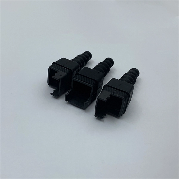
In this post, we'll walk you through practical tips, essential tools, common pitfalls, and the techniques that will help you get your fibre patch cable installations right the first time. Correct patch-cord installation is essential for maintaining low insertion loss, stable return loss, and long-term reliability in both indoor and outdoor fiber networks. Proper handling, routing, cleaning, bend-radius management, and connector alignment ensure that the optical link meets design. Proper connection of fiber optic cables is essential to harness these benefits fully, as even minor errors can lead to significant performance issues like signal loss. This guide addresses expert-certified best practices applied by professionals in the telecommunications, data. Yingda outlines the tools and materials needed to install fiber optic patch cords, as well as a complete step-by-step installation guide and important safety considerations to take. We will also tie this procedure back to the earlier discussion of multi-mode fiber types (OM1 to OM5) and connection. The Flex-Angle boot is designed to bend any angle or direction from straight to 90°. OMC flex angle boots for LC&SC fiber optic connectors are available on any single-mode or multimode patch cord. They are designed so the installer can pre-bend the boot into any direction or angle. Selecting the correct fibre patch lead is crucial for optimising signal performance and.
[PDF]

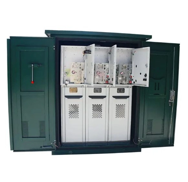
How often you check the enclosure depends on where and how you use it. You must follow rules for dangerous. Explosion proof distribution boxes and electrical enclosures are critical components for ensuring safety in hazardous environments. They are designed to contain internal explosions and prevent ignition of surrounding flammable gases or dust. Since the ATEX Directive came into force, equipment for explosive. We supply certified explosion proof distribution box & Atex Transformer -Appleton, ATKON, CZ, CEAG, brands for safe and reliable industrial use. Flameproof enclosure (Ex d IIB+H2), which can be used as feed distribution equipment in control and distribution system (such as distribution box, switch box of main circuit, control box, terminal box or motor starting box etc. ) ·Enclosure: stainless steel. Equipped with specialized hinge. Ex Industries (exindustries) is a global supplier of advanced hazardous area solutions, offering a wide portfolio of certified products including explosion proof electrical boxes, explosion proof junction boxes, explosion proof lighting, intrinsically safe barrier systems, explosion proof cables. These NEC-rated enclosures are often used to protect your people and parts from explosive risks in plants that handle or make fuel, bulk powders, and chemicals. Plus, they lock out water to keep your electrical components dry. Lift-Off Cover— The removable, screw-secured cover is best for full.
[PDF]
In this video we show you how to dismantle a concrete telecommunications tower with a crane truck. Every health and safety measures at work were strictly comp. PTTG has experienced crews available to help when owners determine they no longer need their tanks, towers, or other structures and require them to be dismantled and removed, including scrap disposal and site cleanup. On occasion, tanks or towers cease to function or become too old to maintain. This can include towers, batteries, internal equipment, hazardous material, and communication shelter removal. We handle each project with safety and sticking to a budget in mind. Cellular tower demolition jobs can be trickier than most jobs. Legalities of what third parties have access to the site can cause issues–issues we will take care of. Our experienced team handles all aspects of decommissioning, including: • Mount & Antenna Removal – Dismantling old equipment with precision. • Microwave Decommissioning – Safely uninstalling.
[PDF]
In this guide, I'm excited to share with you 15 creative and surprisingly simple ways to transform your ugly electrical box from an eyesore into a part of your home you might actually want to show off. There are actually a whole host of creative and, more importantly, stylish ways to conceal your breaker box or electrical panel without blocking access or impeding functionality. But before you get started, make sure you double-check with an electrician and your local codes. Some electrical codes. Either way, here are unique electrical panel cover ideas to give you some inspiration. Don't let an ugly gray metal electrical panel ruin your decor! Check out these creative solutions for covering one in any room (removable, of course). Our editors and experts handpick every product we feature. We may earn a commission from your purchases. Which is exactly where I was struggling, we have an electrical panel directly in our dining room (small space problems). These fellow bloggers turned their electric panel doors from eyesores into focal points and pieces of art.
[PDF]

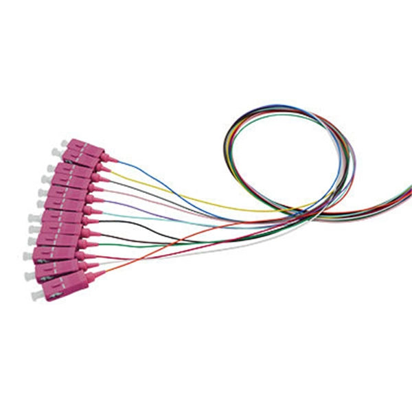
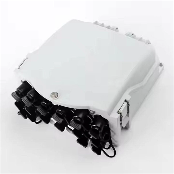
If you are ever in need of checking your ONT, this video will show you how to do so and what it is you are looking for. Always remember to securely close the box afterwards to prevent any damage to the facilities inside. more. A fiber termination box is the standard instrument used in fiber optic networks to connect, secure, and protect optical fibers at the terminating point. It functions as a junction between the incoming fiber cable and the outgoing customer-side fiber cable, where one fiber can be spliced, patched. Open the Fiber optic terminal box. Check and prepare installation tools and accessories. Prepare the cable according to the design. An ONT, or Optical Network Terminal, is the box where your fiber internet connection enters your home to power your fiber network. Your ONT is typically located in your garage, basement or outside your home within a few feet of your home's power box. It serves as a termination point for optical fibers, providing a secure and organized space for connecting and managing fiber optic cables. A fiber pigtail is a specific hardware connection used for cable termination. Proper installation and maintenance of FTBs are essential to ensure the reliability and performance of the network infrastructure.
[PDF]
Download a comprehensive set of Cable Tray Installation CAD Blocks in DWG format, ideal for electrical engineers, MEP designers, and industrial layout planners. Electrical cable tray layout is a ready-to-use CAD block perfect for building services, industrial setups, and electrical projects. This cable tray CAD block is compatible with AutoCAD and other DWG-supported software, allowing precise placement and easy integration into your designs. Save time and. Discover all CAD files of the "Cable trays" category from Supplier-Certified Catalogs ✅ SOLIDWORKS, Inventor, Creo, CATIA, Solid Edge, autoCAD, Revit and many more CAD software but also as STEP, STL, IGES, STL, DWG, DXF and more neutral CAD formats. This collection includes installation details for ladder trays, perforated trays, solid-bottom trays, and wire mesh trays, along with. Tray installation details for the location of a project's electrical wiring; in addition to blocks with different angles that allow the wiring circulation to be identified. Download this FREE 2D CAD drawing of CABLE TRAYS including various widths. This autocad drawing can be used in your mechanical design CAD drawings. dwg format) Our CAD drawings are purged to keep the files. Already Subscribed? Download free cable trays in DWG or CAD block format. Cable tray details.
[PDF]

Excavate the cable at the break point and use a fiber optic cutter to remove the damaged section. Use a high-precision fiber cleaver to prepare the fiber ends for splicing. Step1 : Identify the optical cabinet and network operating center, and find the fiber optic splitter. Step 2: Identify the splitter number. Step 4: Find the optical fiber port and cable sequence that leads to the user. 2) The. Here are the steps to patch a fiber cable. Make sure the connectors are free from dust or dirt and that there is no damage to the cable's. When fiber cables sustain damage, specialized repair techniques help restore connectivity and maintain data integrity. This comprehensive guide outlines professional fiber optic repair protocols that align with industry best practices. Adhering to precise methodologies, we can mend impaired cables. Learn how to splice fiber optic cable step by step in this complete guide! In this video, you'll see the full fiber splicing process — from fiber preparation, cleaving, and fusion splicing to final testing. Whether you're a network technician, IT professional, or telecom operator, you'll find practical steps, tools, and tips to restore. By understanding these key elements and following the outlined steps, you can effectively repair fiber optic cables and maintain the high-performance network necessary for today's demanding communication needs. When it comes to ensuring nice network experiences for users, the condition of a fiber.
[PDF]
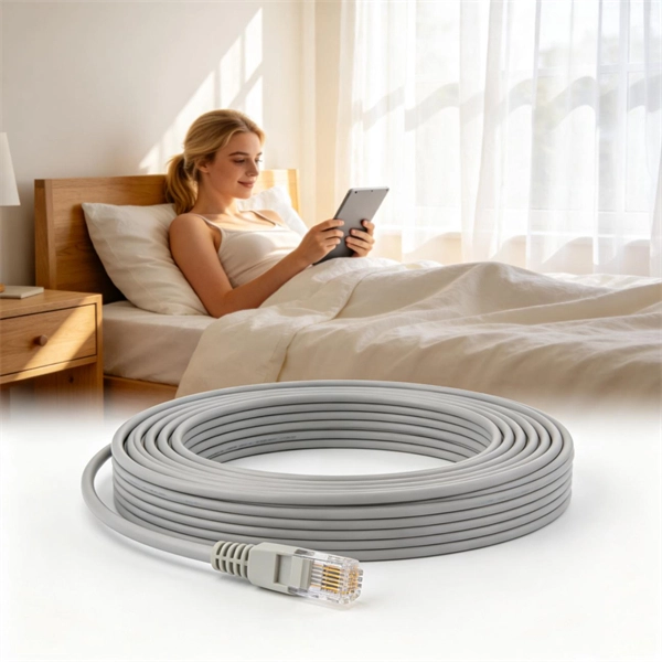
This article will provide an in-depth analysis of outdoor cable types, key selection criteria, core installation steps, critical precautions, as well as subsequent testing and maintenance guidelines, helping you build a robust and durable outdoor optical communication link. Therefore, understanding the characteristics of outdoor fiber optic cables and mastering proper installation methods is crucial. Plan your outdoor fiber installation carefully by surveying the site, choosing the right cable type, and following FOA and OSP standards to ensure reliability. In this video, we'll walk you through the process of establishing a robust outdoor fiber connectivity solution. Follow our guide and establish a r. more Welcome to. Running a cable through an exterior wall can be a daunting task for many homeowners, but with the right tools and techniques, it can be done efficiently and safely. With the increasing demand for high-speed internet and reliable networking, it's essential to know how to properly install CAT 6 cables outdoors. In this article, we'll take you.
[PDF]

The Total Cost of Ownership (TCO) for Passive Optical LAN (POL) is often wrongly seen as high. Meanwhile, Optical LAN can be cheaper in rip & replace use cases, even in brownfield scenarios. Moreover, the long-term return is significant. Hardware and deployment. Often the lower costs are a result of Passive Optical LAN (POL) ability to: The Association for Passive Optical LAN (APOLAN) Technology Committee members recently completed a POL cost comparison study. They did so by analyzing the cost of POL parameters (e. 4-port PoE ONTs, ONTs shared in. The elimination of costly IDFs is one of many capex-reducing elements that users enjoy when they switch to POL, finds recently released cost comparison produced by the Association for Passive Optical LAN (APOLAN). There are no IDFs at this high-end. Passive Optical LAN replaces copper and multi-tier switches with fiber-optic cabling and passive optical splitters based on FTTH GPON/XPON technology. POL transforms a LAN into a simple and flat fiber cabling network. POL covers large building projects and long-distance transmission without the. The Association for Passive Optical LAN (APOLAN) announced the results of it Passive Optical LAN Cost Comparison study, conducted to illustrate the possible economic advantages of POL over traditional enterprise networks based on Category cable.
[PDF]

With the large variety of beamsplitters available, the designer needs to take many factors into consideration. This article and its illustrations will go a long way toward making the correct choice less of a risk. All curves show typical performance. A beam splitter (or beamsplitter, power splitter) is an optical device which can split an incident light beam (e. a laser beam) into two (or sometimes more) beams, which may or may not have the same optical power (radiant flux). It is a crucial part of many optical experimental and measurement systems, such as interferometers, also finding widespread application in fibre optic telecommunications. One beam is typically reflected while the other is transmitted. Beamsplitters are often classified according to their construction: cube or plate. In this blog, we will explore the step-by-step process of using a beamsplitter cube effectively, along with some common applications that benefit from this powerful optical tool. Step-by-Step Guide on Using a Beamsplitter Cube Step 1: Understanding the Cube Orientation: A beamsplitter cube is a. A beam splitter is an optical device that splits beams (such as laser beams) into two (or more) beams. Beam splitters typically come in the form of a reflective device that can split beams into exactly 50/50, half of the beam being transmitted through the splitter and half being reflected.
[PDF]
Spring knot is used to connect cable tray or trunking to channel. Approved and correct fittings are used. Bonding jumper is installed. Tagging/labelling is provided. Installed containments are free of damages. The purpose of this article is to define the sequence and methodology for the installation of electrical cable trays, cable trunking, cable raceways and boxes, junction and pull boxes. These guidelines are not intended to cover all details or variations in cable ladder and cable tray. Hubbell's NEXTFRAME® Ladder Tray is the effective and widely used cable runway that supports and delivers bundles of cable between cabinets, racks, and closets, along walls, and suspended from ceilings. The Ladder Tray features light, rugged, tubular steel construction. It is designed for. bow fittings, etc. ) Of the tray being mounted. Supports should provide strength and working load sufficient to the load require ents of the cable tray system being supported. Structural building members should never be cut, and cable trays should not be installed in hoist ways or where subject to. Welcome to our comprehensive guide on installing wall brackets for different types of cable trays and cable ladders! In this video, we will walk you through the installation process for four different types of wall brackets, specifically designed for cable trays, mesh cable trays, and cable.
[PDF]
