Use a fiber optic stripper to remove the protective jacket from the end of the fiber. Be careful not to nick or damage the fiber itself. This is an outdoor rated fiber that is very. Fiber patch cables can be used with many network devices, such as optical transceiver modules, fiber adapter panels, fiber cassettes, media converters, and other products having fiber optic interfaces. The actual steps may vary depending on the cable and/or connectors. Fiber optic cables are typically damaged in one of two ways: A premade fiber optic cable suffers connector damage when too. However, if the cap is too tight to pull using your finger, you can use a pair of soft-tipped tweezers to remove it gently. Step 2: Using your fingers or the tweezers, grasp the cap's edges. To strip and clean outdoor FO cable, you have to start with the outer jacket. Step 1: Mark the armor (if the cable has armor) with the tip of your knife to note a length sufficient to expose the cable's ripcord, being careful not to go through the armor and cut the ripcords. Step 2: Cut and remove. Gather the required tools before attempting to remove a fiber optic LC connector. A dust cap, a fiber optic connector cleaner, and a lint-free cloth are required. Examine the Connector You.
[PDF]

The LS-SM3101-20C SFP transceivers are high performance, cost effective modules supporting data rate of 125Mbps/155Mbps and 20km transmission distance with SMF. The transceiver consists of three sections: a Cooled EML laser transmitter, a APD photodiode integrated with a trans-impedance preamplifier (TIA). The AFCT-5745NPZ/UPZ Lead-free Singlemode Optical Transceivers have been qualified in accordance to the requirement of Telcordia Document GR-468-CORE under the supervision of Avago Technologies Quality & Reliabil-ity Department. This report summarizes the qualification tests over a range of. Copyright © 2022 GOC-UZ. See our terms of use and privacy policy. Volza's Solution gives you 100x return in Six Months! Use strategic filters to explore Optical transceiver module Import data like a seasoned analyst, uncovering hidden opportunities in the Optical transceiver module import business. Our database includes 321 Import shipments, involving 63 Buyers. Up to now, MEISU has developed various high-temperature resistant optical devices not only with regular SM fiber, but also with PM fiber array by applying special high-temperature coating to the normal PM fiber, providing muiltiple choices for silicon photonic (SiPh) solder reflowable assembly at.
[PDF]
This guide covers the critical steps, from selecting the right electrical cable tray and performing accurate cable fill calculations to managing a safe cable pull through and ensuring all bonding and grounding requirements are met. Article Summary: A compliant cable tray installation requires a thorough understanding of NEC Article 392, proper structural support, and precise installation techniques. But before you lay the first tray or clamp down a single cable, you need a solid plan. This guide breaks down the process step by step. Here is a step-by-step guide on how to install a standard metal cable tray system (e., ladder or perforated type). Before starting, ensure you have. NEMA VE2 addresses cable tray installation and provides information on maintenance and system modification. NEMA VE2 was developed by the NEMA Cable Tray Section, of which MP Husky is a charter member. Ladder Cable Trays Solid side rail protection and system strength with smooth radius fittings and a wide selection of materials and finishes. Maximum strength for long span applications. Welcome to our step-by-step guide on installing cable trays! In this video, we'll explore the different types of cable trays available and provide detailed instructions for their installation. Whether you're an experienced electrician or a DIY enthusiast, this video is perfect for you.
[PDF]
This article will provide an in-depth analysis of outdoor cable types, key selection criteria, core installation steps, critical precautions, as well as subsequent testing and maintenance guidelines, helping you build a robust and durable outdoor optical communication link. Therefore, understanding the characteristics of outdoor fiber optic cables and mastering proper installation methods is crucial. Plan your outdoor fiber installation carefully by surveying the site, choosing the right cable type, and following FOA and OSP standards to ensure reliability. In this video, we'll walk you through the process of establishing a robust outdoor fiber connectivity solution. Follow our guide and establish a r. more Welcome to. Running a cable through an exterior wall can be a daunting task for many homeowners, but with the right tools and techniques, it can be done efficiently and safely. With the increasing demand for high-speed internet and reliable networking, it's essential to know how to properly install CAT 6 cables outdoors. In this article, we'll take you.
[PDF]

This quick-reference guide focuses on what to measure, how to interpret results, and what to do when findings indicate marginal performance. Whether you're a network engineer validating new inventory or an integrator preparing for deployment, knowing how to test optical transceiver modules can save time, reduce failures, and ensure SLA compliance. Unchecked optical modules can cause: Testing ensures compliance with IEEE 802. 3 and MSA. This article provides a comprehensive guide on measuring key performance indicators to evaluate the functionality of optical modules, with a specific focus on the sfp28 transceivers. A comprehensive understanding of the working principle of an optical module is essential for determining the. Evaluating the performance of optical modules is a practical discipline: you must verify optical power and signal quality, confirm electrical/optical compliance, validate link-level behavior under real traffic, and document results in a way that supports reliability engineering. This. The optical module serves as a crucial component in optical fiber communication systems, operating at the physical layer, which is the lowest layer in the OSI model. Its primary function is to achieve optoelectronic conversion by converting electrical signals into optical signals and vice versa.
[PDF]
00 Original price was: $285. Add an LC fiber optic connection to your Blackmagic Studio Camera, Teranex Converter, ATEM hardware, or any other professional device that supports SFP cages with. Help others learn more about this product by uploading a video! Looking for specific info? Would you like to tell us about a lower price? Found a lower price? Let us know. Although we can't match every price reported, we'll use your feedback to ensure that our prices remain competitive. 6G data rates support SD, HD, and 4K resolutions, and the fiber optic communication allows. FiberMall SFP+ Transceivers are hot swapping, cost effective modules supporting data rate of 6Gbps/8Gbps/10Gbps/16Gbps/32Gbps and up to 120km transmission. Learn more Spread the cost of your purchases over 3 to 24 months with an interest rate from 0. There's no fees if you pay on time. All set! You can manage payments in the Klarna app or website Down payment may be required. Klarna Monthly.
[PDF]
Welcome to our step-by-step guide on installing cable trays! In this video, we'll explore the different types of cable trays available and provide detailed instructions for their installation. Whether you're an experienced electrician or a DIY enthusiast, this. Whether you're building a commercial setup or upgrading an industrial plant, proper cable tray installation ensures neat wiring, safe access, and easy maintenance. But before you lay the first tray or clamp down a single cable, you need a solid plan. This guide breaks down the process step by step. Installing a cable tray system requires careful planning to ensure it can support the weight of the cables and adheres to electrical safety codes. Here is a step-by-step guide on how to install a standard metal cable tray system (e., ladder or perforated type). more. The purpose of this article is to define the sequence and methodology for the installation of electrical cable trays, cable trunking, cable raceways and boxes, junction and pull boxes. The method gives details of how the work will be carried out and what health and safety issues and controls that. Cable tray systems are designed for easy installation and to accommodate power, communications, and signal cabling across a variety of applications. When installed and engineered properly, cable.
[PDF]
In this guide, we break down the two core stages of optical fiber manufacturing: preform production (shaping the precursor material) and fiber drawing (transforming the preform into thin, usable fiber). Explore the optical cable manufacturing process. Learn about raw materials, fiber drawing, cabling, and quality control in modern optical cable manufacturing. Is your digital life lagging? Slow streams, dropped calls? The unsung hero of our connected world, the optical cable, might be the key, and. Fiber optic cables are the backbone of today's high-speed internet, telecommunication systems, and data transfer technologies. Fiber optic technology has revolutionized the way information is transmitted, offering numerous advantages over traditional copper wiring. What makes fiber optic cables special is their ability to. The production of optical fiber is a precision-driven process that transforms raw materials like silicon tetrachloride into ultra-thin, high-performance fibers capable of transmitting terabits of data over thousands of kilometers. This manufacturing journey directly impacts the fiber's mechanical.
[PDF]
The typical thickness of a glass core can range anywhere from 8-10 um (microns) for single-mode and 62. 5-50 um for multimode; these core sizes are the most prevalent ones utilized in the telecommunications industry. The core of a conventional optical fiber is the part of the fiber that guides the light. It is a cylinder of glass or plastic that runs along the fiber's length. The core is surrounded by a medium with a lower index of refraction, typically a cladding of a different glass, or plastic. The light is transported along the optical fiber via its smallest and most crucial component, which is called the core. However, they are composed of many components, each constructed from advanced materials to guarantee the quick and reliable transmission of data. So, let's break it down! The core is the primary part of a Fiber optic cable. It's responsible for. The 8 Core Multimode Outdoor Fiber Optic Cable is designed for high-performance data transmission in various outdoor environments, making it an ideal choice for telecommunications, networking, and data center applications. We supply single mode GYTS fiber optical cable and multimode GYTS fiber optic cable, fiber strand from 2 cores to 432 cores. A related GYTA type cable is available. This advanced cabling solution allows fast, secure data transfer and telecom over long distances. Understanding the components within a fiber optic cable enables.
[PDF]
Step-by-step on-site guide: learn how to plan, mark, support, and install cable trays correctly, from shop drawing approval to final checks. Method Statement installation of Cable Trays and Ladders - Planning Engineer FZE. The Cable Tray system is installed in electrical rooms, plant rooms, and service. Whether you're building a commercial setup or upgrading an industrial plant, proper cable tray installation ensures neat wiring, safe access, and easy maintenance. But before you lay the first tray or clamp down a single cable, you need a solid plan. This guide breaks down the process step by step. In order to get it right, installers are supposed to adhere to a plan that ensures that wires are kept cool and the building is stable. The beginning of success is to review the Bill of Quantities (BOQ) so that. In this post, we will see together how to install cable tray on-site. Firstly, we need an approved shop drawing that shows the cable tray route, its dimensions, installation height, support system, the number of layers of these trays, and the type of systems they will serve. The key requirements for cable tray installation include: Incorrect installation can lead to overheating, cable damage, or system failure. This guide covers the critical steps, from selecting the right electrical cable tray and performing accurate cable fill.
[PDF]

This guide delves into the structure and working principle of fiber optic connectors and outlines the critical steps for creating a successful connection. There are many types of fiber optic connectors, including SC, LC, FC, ST, D4, MU, MT/MPO, etc. These connectors can be divided into single-mode and multi-mode fiber optic connectors according to their structure and purpose. To learn more about the types of fiber optic connectors, click here: Types. Proper connection of fiber optic cables is essential to harness these benefits fully, as even minor errors can lead to significant performance issues like signal loss. This article will guide you through the necessary tools, materials, and methods on how to connect fiber optic cables effectively. At the heart of any robust fiber optic network lies a crucial process: Preparing a fiber cable for termination of a connector or splice. Fiber optic connectors play an essential role in the realm of optical communication, enabling seamless connections between fiber optic cables. We terminate fiber optic cable two ways - with connectors that can mate two fibers to create a temporary joint and/or connect the fiber to a piece of network gear or with splices which create a permanent joint between the two fibers. Whether you are installing a new network or repairing an existing one, ensuring a proper connection is crucial for maintaining optimal signal.
[PDF]

Learn how to install a fiber optic termination box step-by-step for FTTH projects. Covers mounting, splicing, routing, labeling, and testing for indoor/outdoor use. Installing a fiber optic termination box is one of those jobs that looks simple on paper, but it's easy to do poorly in the field. If you do not have relevant experience and skills, it is recommended to ask a professional to install it. Preparations: Before installation. How to install the FTTH terminal box? - YouTube This kind of box are used in the end termination or residential building sand villas, to fix and splice with pigtails, can be installed on the wall. When it comes to ONT installation, you've got two main options: Indoor ONTs are installed inside your home, typically in a utility room, basement or another centralized spot. Both options have their advantages, and the choice. A fiber termination box is the standard instrument used in fiber optic networks to connect, secure, and protect optical fibers at the terminating point. To install a junction box correctly, choose a box that matches the wiring method and environment, mount it securely, bring cables in.
[PDF]

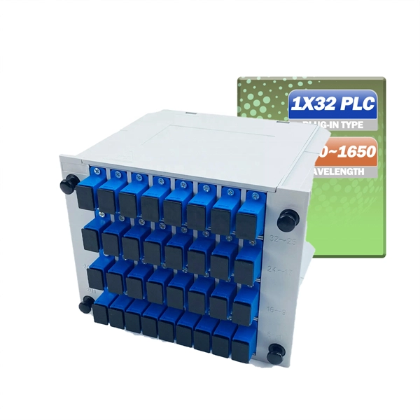
Product Range: PLC splitters, FBT splitters, fiber optic adapters, patch cords Price Range: $5 to $150 depending on splitter ratio and specs Overview: TTI Fiber is a global supplier known for quality optical components. FBT (Fused Biconical Taper) Fiber Optic Splitters. These devices splits the fiber optic signal from a single Input to two Outputs. Available in 50/50, 30/70, and 90/10 spit ratios. A fiber optic splitter is different from WDM. WDM can divide the. FBT (Fused Biconic Taper) Coupler Splitter is a commonly used fiber optic coupler and splitter for distributing optical signals to multiple output channels. FBT splitters are reliable and cost-effective, typically used for smaller split ratios like 1x2 or 1x4. The physical packaging or form factor of a splitter is crucial. FBT Coupler Splitters is widely accepted and used in passive optical networks, especially for instances where the split configuration is smaller (1×2, 1×4, etc. FBT is the traditional technology in which two fibers are placed closely together, typically twisted around each other and fused. FBT Fiber Splitter, also known as a fiber optical coupler, separates fiber optic light into many portions using a predetermined ratio. Unlike PLC splitters, FBT splitters employ distinct splitting methods and may be constructed using singlemode, multimode 62. 5, or multimode 50 fibers.
[PDF]

The maximum split ratio of the FBT splitter is as high as 1:32, which means that one or two inputs can be divided into outputs of up to 32 optical fibers. By dividing a single optical signal from a central Optical Line Terminal (OLT) into multiple outputs for Optical Network. In this guide, you'll learn how fiber splitters function in PON networks, the difference between PLC and FBT types, and how to choose the best model for your rollout in 2025. What Are Fiber Optic Splitters in PON? Fiber splitters are passive devices that divide one optical input signal into. FTTH relies on Passive Optical Network architecture, which enables one fiber leaving the central office to serve multiple subscribers through optical splitting. This structure eliminates the need for powered elements in the distribution segment, reducing operational costs while ensuring high. Optical splitter is an integrated waveguide optical power distribution device that serves to split optical signals. It is widely used in passive optical networks (such as EPON, GPON, BPON, FTTX, FTTH, etc. ) and plays an important role. When an optical signal is transmitted in a single-mode fiber. The FTTH network serves as the infrastructure enabling data transmission in the form of light signals over optical fiber from the operator's switching equipment directly to a home or business. Accurately understanding the principles, differences, and applicable boundaries of.
[PDF]

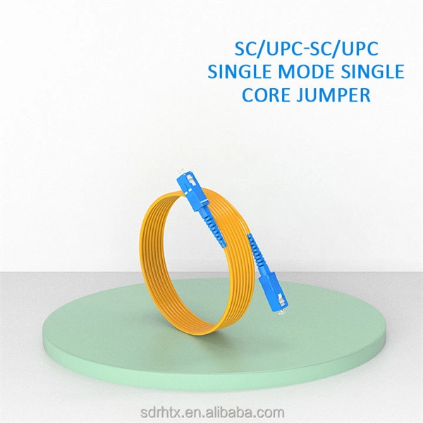
One of the core advantages of MPO patch cords is their high-density integration. Traditional patch cords have only 1-2 cores per cord, while MPO patch cords can integrate 12-48 cores, enabling multi-port connections with a single cord. Fiber cores are the heart of fiber optic cables, transmitting light signals that carry data. Made from either high-quality glass or plastic, the core plays a critical role in determining the cable's performance. The total number of cores for a 1pc fiber patch cable is calculated as the number of. Multi-core patch cords are fiber assemblies containing multiple fibers within a single cable jacket, typically available in 4, 6, 12, and 24-fiber configurations. The outer sheath is clearly marked with core count indicators. MTP/MPO cables are a class of high-density multi-core fiber optic connectivity solutions widely used in data centers and telecom networks, which are designed to achieve fast connection of multi-core fiber optics through a single interface. In the context of accelerating digitalization, the rational. The 16-core MPO patch cord, a high-density optical fiber connector, has become an ideal choice for 400G networks and beyond due to its superior optical performance, flexible compatibility, and efficient cabling capabilities. This report analyzes the key technical parameters, primary application.
[PDF]