In this blog, we'll walk through the standard procedures for installing racks and assembling MPO systems in modern data centers. Before any hardware is installed, detailed planning is essential. Rack placement must consider airflow, power distribution, cable routing, and physical. Proper installation of components in a data center server rack is crucial for optimal performance, efficient maintenance, and long-term reliability of your IT infrastructure. The term breaks down into two distinct phases: “racking” involves assembling and mounting servers, switches, storage devices, and networking equipment into. Best Practices for Data Center Rack and Stack Installation in 2025. Data centers are the backbone of modern technology, and ensuring their infrastructure is installed correctly can significantly impact performance and scalability. Data. However, before you get down to installation itself, it's necessary to prepare for it. A preparatory stage includes several important pre-installation steps that ensure smooth and durable functioning. These include: Choosing the right rack type. Server furniture differs a lot. Modern manufacturers. Four-Post Racks To mount two-post racks, the equipment has to be bolted to two vertical posts, in most cases at the front. They are simple, cheaper than other types, and occupy less space. They are a good choice for small IT rooms or closets with minimal depth requirements and lightweight devices.
[PDF]
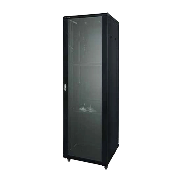
Encuentra opciones de almacenamiento y organización en Gabinetes, Racks Servidores y Sistemas de Cableado Estructurado para Redes de Voz y Datos de calidad. Optimiza tu red en Costa Rica. DURABLE - Crafted from cold-rolled steel with a protective black powder coating, the 6U NavePoint Performance Series network cabinet provides sturdy, reliable housing for network and server equipment. Capable of supporting up to 130 lbs, it's an ideal, durable solution for installers working on. TecnoBonilla. com es la mejor fuente para Rack Servers en Costa Rica. Para más información, póngase en contacto con nosotros en 6286-7654.
[PDF]
Rack height is measured in rack units (U), where 1U equals 1. Common rack formats include: 24U and below — typical for branch offices or small server rooms. Below is a comprehensive, fully detailed guide covering all standard server rack sizes, form factors, height considerations, depth classifications, and best-practice configuration approaches for professional environments. What Is a Server Rack? Understanding the Core Structure A server rack is a. This comprehensive blog post demystifies the "U" unit in network server accessories—the standard measurement that defines the height of equipment in server racks. A 2U server occupies two rack units, while a 4U server takes up four. Each rack is equipped with mounting rails. A “Rack Unit” (U) is a standard height measure for mounting equipment in a server rack. This article explains definition, planning, installation tips, and trends. At Secure Gates Inc., we provide high-quality 6U, 9U, and 12U Network Rack Cabinets designed to meet the unique needs of professionals, businesses, and data centers. In this blog post, we'll explore what network rack cabinets are, their key benefits, and help you decide which size— 6U, 9U, or 12U. U (rack unit, RU) is a unit of equipment height in a 19" rack. Important: U describes height only, but a server's real "capabilities" are also determined by chassis depth, internal layout, airflow, rails, power, and expansion (PCIe/risers, NVMe.
[PDF]
This guide provides instruction on how to install and configure your MS130R series switch. For more switch installation guides, refer to the switch installation guides section on. This guide provides step-by-step instructions for installing two common types of industrial switches: rack-mount, and DIN-rail switches. Choose the Installation Location: Select an appropriate spot on the DIN rail for mounting. This chapter describes how to start your switch and how to interpret the power-on self-test (POST) that ensures proper operation. No prior experience needed—just follow along and you'll have your switch installed and running in minutes. more In this video you'll see a complete, step-by-step guide to mounting. This typeface indicates command syntax, or represents information as it is displayed on the screen. When you see the word enter in this guide, you must type something, and then press the Return or Enter key. Do not press the Return or Enter key when an instruction simply says type. Here, we explore the four most common installation methods for industrial switches: Desktop installation is the most straightforward approach— placing the switch like a small box directly on a table, control panel surface, or equipment rack without extra fixtures. Simple setup: No tools required.
[PDF]

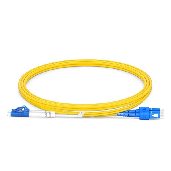
This comprehensive guide will explore the importance and benefits of this integration, provide an understanding of fiber optic cable and Ethernet ports, discuss their compatibility, and offer a step-by-step process for connecting them. Proper connection of fiber optic cables is essential to harness these benefits fully, as even minor errors can lead to significant performance issues like signal loss. This article will guide you through the necessary tools, materials, and methods on how to connect fiber optic cables effectively. Using an optical cable involves connecting it to the right equipment, ensuring proper installation, and testing the system for optimal performance. Here's a step-by-step guide on how to use optical cable effectively: 1. Check Compatibility of Equipment Ensure that your equipment (e., network. One powerful solution to achieve these goals is by connecting fiber optic cables with Ethernet ports. This comprehensive guide combines industry standards with field-tested practices to ensure you achieve a rock-solid. These transceiver modules are hot-swappable input/output (I/O) devices that plug into 100BASE, 1000BASE and 10GBASE ports (for SFP+), which connect the module port with the fiber-optic or copper network. The SFP transceiver modules are hot-pluggable I/O devices that plug into module sockets. The number one cause of signal loss in optical fiber installations is dirt on.
[PDF]

Here's a step-by-step guide to help you properly arrange fiber optic patch panels in a data center environment. Before installation, assess your network's current and future needs:. This guide outlines the key steps and considerations for effective cable management in fiber optic systems. Managing fiber optic patch cables requires strict adherence to technical standards due to the unique material properties of the cables. Even the most advanced optical transceivers can only perform at their peak when paired with properly installed, clean, and precisely managed fiber. Knowing the ins and outs on fiber patch cords and how they are important in server racks Glass fiber patch cords are very slim cables that are excellent at transmitting information quickly and in great quantity. It is essential when racks of servers are used, to maintain a strong and secure. In this configuration, a permanent link is installed between QuickNetTM Patch Panels in the switch/network cabinet and the server or storage cabinets. The most common, flexible, and upgradeable QuickNetTM Fiber Solution is shown in Figure 2, below: In this configuration, permanent links are. Patching fiber optic cable involves carefully splicing two ends together to repair a break or extend a cable run. Here's a breakdown of the process: Assess the Damage and Prepare: Carefully inspect the damage to determine if a patch is feasible. Severely damaged cables may require replacement.
[PDF]
This section provides an overview for server racks as well as their applications and principles. Are you choosing the right server rack manufacturer for your business? Whether you need racks, wall mounted network cabinets, or server cabinets, there are a variety of options available in the United States. Here are the top-ranked server rack companies as of April, 2026: 1. Cyber Power Systems USA. Some of the features include one-piece hinged covers, adjustable vented shelves, vertical cable management, floor mounting holes, integral front waterfall tops, pre-drilled holes, heavy gauge steel frames and vertical mounting-hole patterns. more+ Indoff is estimated to have 200-499 employees. At Rackmount Solutions, we provide rack, cabinet, and physical infrastructure systems designed with safety, protection and adaptability in mind. From open-frame racks to fully enclosed cabinets, our solutions keep equipment secure, organized, and ready for growth. We believe connectivity is the. Discover leading server cabinet manufacturers in the USA: Eabel, Hubbell, and others. Innovative, custom IT infrastructure solutions for diverse needs. They help to organize and secure important equipment by housing them. By selecting a reliable server cabinet manufacturer, you can make sure your equipment gets the best performance which is needed for data centers, networks and IT.
[PDF]
The typical cost of 1U space in a 45U server cabinet is $55. Therefore: Average cable management cost is . Basic cable management systems (cable trays, ties): $200 to $1,000 per rack. Power and Cooling Infrastructure Power Distribution Units (PDUs): $200 to $1,500 per unit, depending on capacity. 73/U The. Durable & Easy to Install: Made from sturdy plastic for long-term use in IT environments. Installs easily on standard rack rails using the included M6 screws-no special tools required Each item has a unique code that we verify before shipping. com Return Policy: Amazon. com. Sysracks offers a wide array of data closet cable management products for different devices: Horizontal managers: Our 1U wire managers are designed to suit any 19” cabinet. This allows structured routing of twisted-pair wires and patch cords and ensures the correct cord radius to prevent twisting. Shop top-quality rack cable managers for efficient data center wiring. Get a horizontal/vertical cable manager to safely organize and protect your cables. Our 1U and 2U cable managers reduce slack, improve airflow, and create clean, serviceable rack layouts designed for scalability.
[PDF]
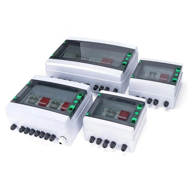
This video shows real on-site footage of electrical installation, demonstrating safe and standardized wiring methods used by professionals. Whether in a home or an industrial facility, this box keeps your electrical setup organized, functional, and efficient. However, the key to a safe and reliable system lies in proper installation. If it's done poorly, you risk short circuits, fire hazards, or system failure. Done right, it ensures. Whether you are an electrical contractor or a construction brigade, knowing how to properly and safely install distribution boxes is the basis of ensuring the safe operation of the entire system. This article details the process of installing them, which helps you comprehend distribution boxes. How to Install a Cable Distribution Box Safely and Correctly? In modern electrical systems, cable distribution boxes (also known as electrical distribution boxes or distribution boxes) play a crucial role as the key hub for managing, distributing, and protecting circuits. Can I convert the circuit wiring in my shop to be used for different equipment? Converting Existing Circuit Wiring in a Workshop or Garage. There is a demand for more RCD protection of final circuits, affect Type B MCB distribution boards and their protective d bar arrangement designed to accept single and/or double pole OCPDs.
[PDF]
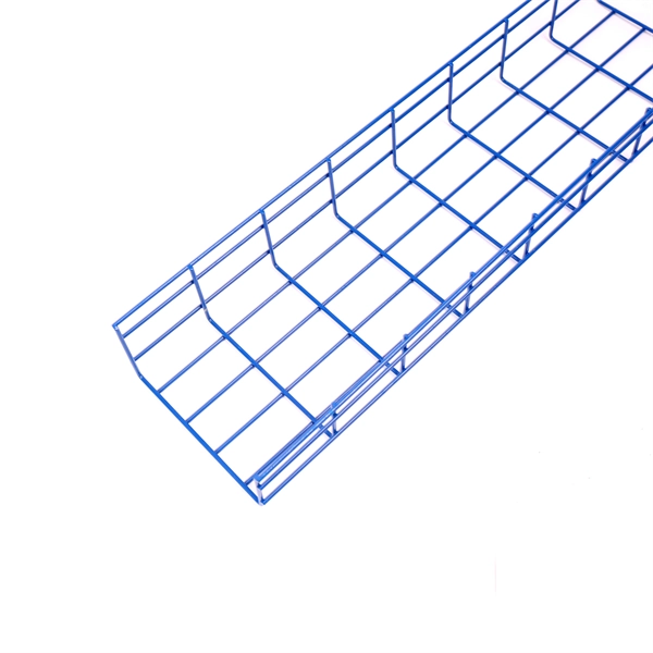
Download a comprehensive set of Cable Tray Installation CAD Blocks in DWG format, ideal for electrical engineers, MEP designers, and industrial layout planners. Electrical cable tray layout is a ready-to-use CAD block perfect for building services, industrial setups, and electrical projects. This cable tray CAD block is compatible with AutoCAD and other DWG-supported software, allowing precise placement and easy integration into your designs. Save time and. Discover all CAD files of the "Cable trays" category from Supplier-Certified Catalogs ✅ SOLIDWORKS, Inventor, Creo, CATIA, Solid Edge, autoCAD, Revit and many more CAD software but also as STEP, STL, IGES, STL, DWG, DXF and more neutral CAD formats. This collection includes installation details for ladder trays, perforated trays, solid-bottom trays, and wire mesh trays, along with. Tray installation details for the location of a project's electrical wiring; in addition to blocks with different angles that allow the wiring circulation to be identified. Download this FREE 2D CAD drawing of CABLE TRAYS including various widths. This autocad drawing can be used in your mechanical design CAD drawings. dwg format) Our CAD drawings are purged to keep the files. Already Subscribed? Download free cable trays in DWG or CAD block format. Cable tray details.
[PDF]

We stock a large selection of Rack & Cabinet Cable Organizers, including new and most popular products from the world's top manufacturers including: APC, Siemens, Hammond, L-com & Panduit R1316. Fibox Arca Cabinet - the. Explore Schneider Electric open and enclosed server rack and network rack solutions for a variety of environments including data centers, server rooms, network closets, offices, industrial, and specialty applications. Unique colors, input cord plugs and outlet configurations done simply and. Cabinets, open racks and containment are essential part of cabling solutions deployed by RWL. The range of cabinets starts at Comms cabinets and continues through to full load rated Server cabinets. Beyond this we have bespoke cooled cabinets designed as per the requirement of the client. Our. Rackmount. IT specializes in custom rack mount kits for various desktop security appliances, having produced 350,000 kits for brands like Cisco, Fortinet, and Palo Alto Networks. Their products ensure secure installation and optimized airflow, preventing network interruptions. Buy Cable Management at the best price from Norden Communication, one of the leading manufacturers and suppliers of Cable Management in Netherlands. Anixter is your source for Racks, Cabinets and Enclosures products. We offer high-quality cable trays for the organised control and protection of cabling, ladder racks for safe walkways, and closed conducts for maximum protection of critical.
[PDF]
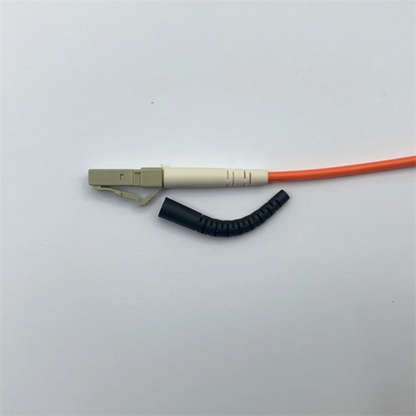
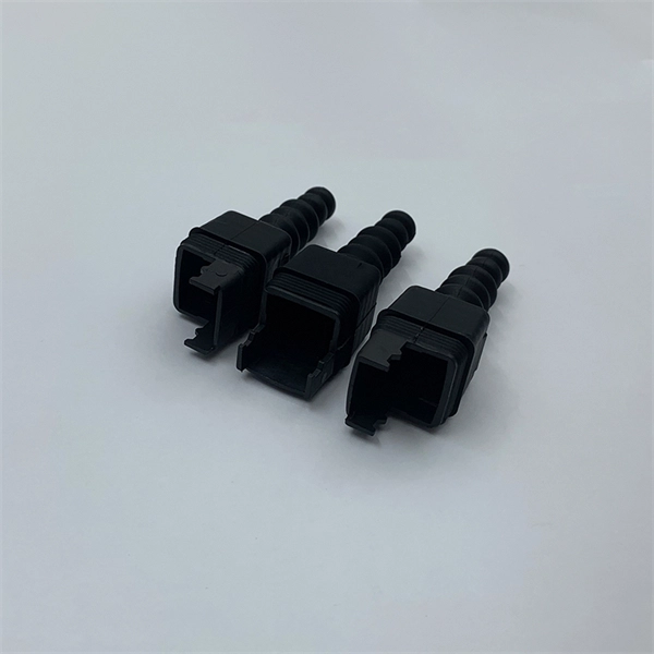
LC Connectors: Press the latch mechanism and gently pull the connector out. This guide outlines proper methods to safely remove fiber optic cable from modems in your home or office. As an experienced technology writer who has covered broadband advancements for over a decade, I aim to provide readers with trustworthy instructions endorsed by industry experts. Having. Unplugging a fiber optic cable from a modem is a task that requires careful handling to avoid damaging the delicate fibers within the cable. Fiber optic cables are different from traditional copper cables, as they use light to transmit data, and the connectors are more sensitive. This is a popular video tutorial that is often requested by viewers. Fiber optic cables are delicate and require specific handling procedures to maintain their performance and longevity. Is this something that requires a Verizon support tech or can I do it? If so is it as simple as disconnecting and reconnecting or would I have to call support to "reinitiate" my setup. Not my pic, but didn't feel like moving the. Unicom's Wireless Router is a multi-function device providing the following services: • Shared Broadband Internet Access for all LAN users. Page 5 All manuals and user guides at all-guides. com • Virtual Servers. This feature allows Internet users to access Internet servers on your LAN.
[PDF]

Fiber Optic Welding How To Joint Fiber Optic Cablesplicing fiber optic cable,fiber optic splice,fiber optic,fiber optics,fiber splice,how to splice,fibre opt. The optical fiber connection adopts the fusion splicing method. The whole process is similar to the welding of metal wires, and it is generally carried out by electric isolation. At the moment, there are two methods of connection: Thermal welding of optical fibers consists in bringing the ends of the conductor to melting using a fiber optic splicer, and more specifically - located inside the electrodes. The welded ends are then pressed and a weld is formed. The most work is waiting for installers, whose tasks can be divided into several stages: In this part, we will deal with the second stage, i. welding, which is considered to be one of the most difficult parts of installers' work in. Open the stripping tube and wipe the grease on the optical fiber with toilet paper and alcohol cotton. On the welding disc, make the optical fiber precoil first and cut the optical fiber into an appropriate length to facilitate the coil fiber work after welding. Add heat shrink tube. Procedure. Another method is to use the so-called mechanical welding. It uses special parts that are prepared in advance to connect the two ends. Thanks to this, you can connect two ends of the cable with a ready-made splice, without the need to use an optical fiber splicer. While this method may appear to be.
[PDF]

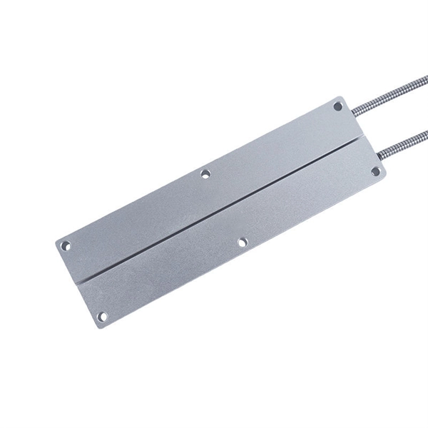
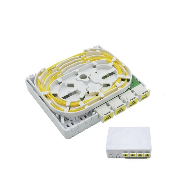
The compact 1 port ftth fiber termination box can hold 2 cores splicing, termination and coil up to 30 meters long for cable management in FTTH network. The 1 port fiber termination box is available for fiber optic cable coiling, it is great to connect optical cable and pigtail and protect fiber splices from damage. It is small, lightweight, and offers the function of fiber splicing, storage, and termination, mainly used in residential buildings. The maximum distance for single mode fiber optic cable can extend up to several hundred kilometers, making it ideal for long distance data transmission. One type of single mode fiber is known as “G. 652,” which is commonly used in telecommunications networks. Here are some general guidelines: 1. The shorter distance accounts for the. A fiber optic distribution box (FDB) is a protective enclosure for managing fiber optic cables. It organizes connections, splices fibers, and distributes signals in networks like FTTH (Fiber-to-the-Home) or FTTB (Fiber-to-the-Building). It acts as a central point for terminating, splicing, and distributing these cables, providing necessary protection and. The Fiber Optic Association, Inc. (FOA) was founded in 1995 to help develop the workforce to build the fiber optic networks to support a rapid expansion in communications and the Internet. The charter of the FOA was to promote professionalism in fiber optics through education, certification, and.
[PDF]

Optical modules (also known as fiber optic transceivers) are essential components in modern communication networks, enabling high-speed data transmission by converting electrical signals into optical signals and vice versa. Among various optical module form factors, SFP (Small Form-Factor Pluggable). A fiber optic transceiver (also called an optical transceiver) is a compact module that both transmits and receives data signals through optical fibers. It serves a dual purpose — transmitting electrical signals as light pulses and receiving light pulses to convert them back into electrical form. An optical module usually consists of an optical transmitting device (TOSA, including a laser), an optical receiving device (ROSA, including a photodetector), functional circuits,main control circuit board (PCBA), housing and optical (electrical) interface and other components. How do optical. At the heart of fiber optic technology lies a crucial component: the optical transceiver. Let's explore the key aspects of optical transceivers to help you navigate.
[PDF]
